When will the CPU or PCH shoot out the PM_SLP_S4_L signal?
This question burdens a lot of component level repair technicians. This article discusses the prerequisites that must be met before the Intel CPU/PCH outputs PM_SLP_S4_L. In order to understand the PM_SLP_S4_L signal, we need to know a litttle bit of Intel CPU/PCH design. Once you understand the PM_SLP_S4_L timing, a logic board with missing PM_SLP_S4_L signal issue is not hard to deal with.
There are two sets of PM_SLP_S4_L prerequisites. Intel 1st to 5th generation CPUs use the same set of prerequisites called 11+1 conditions. Intel 6th generation onward CPUs use a different set of prerequisites called 13+1 conditions (discuss in a separate article). Intel and Apple use different naming systems. We use the Apple naming system by default. Since Apple uses different names referring to the same Intel CPU/PCH signal in different models, we use MacBook Air 2015 A1466 Haswell-ULT CPU 820-00165 schematics here as an example.
Intel 1st to 5th generation CPUs 11+1 prerequisites for PM_SLP_S4_L:
| Apple Name Notation | Intel Name Notation: |
|---|---|
| PPVRTC_G3H | (VCCRTC) |
| RTC_RESET_L | (RTCRST#) |
| PCH_SRTCRST_L | (SRTCRST#) |
| PCH_INTVRMEN_L | (INTVRMEN) |
| PCH_DSWVRMEN_L | (DSWVRMEN) |
| SYSCLK_CLK32K_RTCX1 | (RTCX1) |
| PP3V3_S5 | (VCCDSW3-3) |
| PM_DSW_PWRGD | (DPWROK) |
| PP3V3_SUS | (VCCSUS3) |
| PM_BATLOW_L | (BATLOW#) |
| PM_RSMRST_L | (RSMRST#) |
| PM_PWRBTN_L | (PWRBTN#) |
If PM_SLP_S4_L missing, we need to check these before replacing the CPU/PCH.
When all the 11 prerequisites are met, once you press the power button on the keyboard to generate the PM_PWRBTN_L signal, or connect a charger to the logic board to generate the SMC_ADAPTER_EN signal, the CPU/PCH will shoot out PM_SLP_S5_L, PM_SLP_S4_L and PM_SLP_S3_L to enable S4, S3 and S0 state power rails.
In most models, Apple does not utilise PM_SLP_S5_L signal so we just ignore it. Here we emphasise on the S4, S3 signals. The PM_SLP_S4_L signal enables the S3 state power rails including the memory power rail. The PM_SLP_S3_L signal enables the S0 state power rails including the CPU core power rail.
- PPVRTC_G3H (VCCRTC) – real-time clock circuit power supply. PPVRTC_G3H voltage is 3.3V.
- RTC_RESET_L (RTCRST#) – real-time clock circuit reset signal. RTC_RESET_L voltage is 3.3V.
- PCH_SRTCRST_L (SRTCRST#) secondary real-time clock circuit reset signal. PCH_SRTCRST_L voltage is 3.3V.
- PCH_INTVRMEN_L (INTVRMEN) – Intel CPU/PCH internal voltage regulators 1.05V and 1.5V enable signal. PCH_INTVRMEN_L voltage is 3.3V.
- PCH_DSWVRMEN_L (DSWVRMEN) – Intel CPU/PCH deep sleep well(power) voltage regulator enable signal. PCH_DSWVRMEN_L voltage is 3.3V.
- SYSCLK_CLK32K_RTCX1 (RTCX1) – clock signal for RTC circuit. It can be measured by an oscilloscope. The SYSCLK_CLK32K_RTCX1 clock frequency is 32KHz.
- PP3V3_S5 (VCCDSW3-3) – deep sleep mode power rail. PP3V3_S5 voltage is 3.3V.
- PM_DSW_PWRGD (DPWROK) – deep sleep mode power good signal. PM_DSW_PWRGD voltage is 3.3V.
- PP3V3_SUS (VCCSUS3) suspended mode(shallow sleep mode) power rail. PP3V3_SUS voltage is 3.3V.
- PM_BATLOW_L (BATLOW#) – SMC monitors the status of the battery. If the battery voltage is low, SMC will prevent the MacBook from power-up. PM_BATLOW_L voltage is 3.3V.
- PM_RSMRST_L (RSMRST#) – It stands for “resume reset”. It means the system is ready for resuming from suspended mode (sleep mode) to power on mode. PM_RSMRST_L voltage is 3.3V.
- PM_PWRBTN_L (PWRBTN#) – power button on/off control signal. It is a high-low-high pulse signal. PM_PWRBTN_L voltage is 3.3V. If the logic board is connected to a battery, you need to press the power button on the keyboard to send the pulse signal to the CPU/PCH (via SMC). If you connect the logic board to the charger without connecting the battery, once SMC receives the SMC_BC_ACOK from charging circuit power management IC u7100, SMC will output SMC_ADAPTER_EN (ACPRESENT). In this case, the signal SMC_ADAPTER_EN will act as the same as PM_PWRBTN_L. In other words, the PM_PWRBTN_L is not always a “must” in some situation. It is why we call it “+1″ condition.
PM_SLP_S4_L voltage
PM_SLP_S4_L is not a power rail, it is a control signal output by the PCH or CPU. The PM_SLP_S4_L signal voltage is 3.3V. PM_SLP_S5_L and PM_SLP_S3_L signal voltages are all 3.3V as well. PM_SLP_S4_L plays a very important role in MacBook power-on process. It is a power management control signal being used to transit the Macbook from standby state (S5) to power-on state (S0). A lot of MacBook power issues are related to this PM_SLP_S4_L signal missing.
Lists of other important power rails and control signals and their voltage
- PP5V_S3 power rail voltage is 5V
- PP3V3_S3 power rail voltage is 3.3V
- PP1V8_S3 power rail voltage is 1.8V
- PP1V2_S3 power rail voltage is 1.2V
- VBUS power rail voltage is 5V
- PP1V05_S0 power rail voltage is 1.05V
- PP1V5_S0 power rail voltage is 1.5V
- PM_SLP_S3_BUF_L control signal voltage is 3.3V
- ALL_SYS_PWRGD control signal voltage is 3.3V
- SMC_DELAYED_PWRGD control signal voltage is 3.3V
- PM_PCH_PWROK control signal voltage is 3.3V
- PCH_PWROK control signal voltage is 3.3V
- CPU_VCCST_PWRGD control signal voltage is 1.05V
- PM_PCH_SYS_PWROK control signal voltage is 3.3V
- PLT_RESET_L control signal voltage is 1.05V
In the following case studies of Mac logic board repairs, we will apply this PM_SLP_S#_L timing knowledge in each case to quickly identify the problems. Say goodbye to the old trial-and-error problem solving approach, adopt this advanced “measure, think, pinpoint and replace” approach. You will not only increase the success rates but also build up solid knowledge on logic board repair. This knowledge, in turn, will significantly increase productivity.
Case Study 1
MacBook Model: A1278 2011 820-2936
Fault Description: water damaged, no power, PP3V3_S5 present, PP5V_S3 missing.
Diagnosis: Measure the PP5V_S3 enable signal P5VS3_EN_L, the voltage is 3.3V, not ok. It should be low (EN_L means low-enable). Trace P5VS3_EN_L to Q7911 and find out the PM_SLP_S4_L voltage is 0V. This is a PM_SLP_S4_L missing issue.

Analysis: The 11+1prerequisites must be met before the Intel CPU/PCH outputs PM_SLP_S4_L. If all the prerequisites are ok, then we will consider replacing the PCH u1800. The further measurement indicates PPVRTC_G3H is 1.5V, not ok. It should be 3.3V. The suspect chips are:

Micro Soldering: We spot watermarks (very little mark, the board must have been ultrasonically cleaned by someone) on the clock chip u2800, so we replace it first. After that, the board is fully functional. In a situation like this, we always replace the easy one first. If replacing the clock chip u2800 did not solve the problem, we will remove the resistors on the PPVRTC_G3H power line before replacing the PCH. Replacing the PCH needs a BGA rework station and related BGA rework skills and the cost of the repair will be much higher.
Learn By Example: If we did not perform the measurement before replacing the suspected u2800, we will get this statement: “The faulty clock chip u2800 caused PM_SLP_S4_L missing.” If we did the measurement before replacing u2800, we will get a much more detail statement: “The clock chip u2800 did not output enough voltage to power up PCH RTC circuit, so the PCH will not shoot out PM_SLP_S4_L”. Next time if we encounter a similar situation that the PCH or the resistors on the PPVRTC_G3H line pull down the voltage and cause PM_SLP_S4_L missing, we will handle the situation with ease. A statement like”The faulty clock chip u2800 caused PM_SLP_S4_L missing” is never enough for the advanced technicians and engineers.
Five of the twelve prerequisites are related to the clock chip, PPVRTC_G3H, RTC_RESET_L, PCH_SRTCRST_L, PCH_INTVRMEN_L and SYSCLK_CLK32K_RTCX1. So the clock chip should be the first chip to check if you get a PM_SLP_S4_L missing logic board. Newer model 2016 onward MacBooks use a new clock chip SLG3AP3444 and it no longer outputs power rail to RTC circuit. But if you understand the principle, no matter what chip is used, you still can trace back to it by searching the PPVRTC_G3H (VCCRTC) power rail. Understand the principle and build up a personal knowledge database gradually is a “must” for a component level repair engineer.
Case Study 2
MacBook Model: A1502 2015 820-4924
Fault Description: water damaged, no power, PP3V3_S5 present, PP5V_S3 missing.
Diagnosis: Trace PP5V_S3 enable signal P5VS3_EN = 0V not ok. It should be high 3.3V. Trace P5VS3_EN to R8175 and R8179 and find out the PM_SLP_S4_L is missing (0V).

Analysis: Check the 11+1prerequisites, all are good except the PM_BATLOW_L is low 0.9V. This signal is from SMC. If SMC detects a battery is connected, it will use SMBUS_BATT_SCL/SDA to get the status data of the battery. If the battery voltage is lower to a preset value, SMC will keep PM_BATLOW_L as low until the battery is charged and the voltage is above the preset value. If SMC detects no battery connected, it will assume the battery is ok and output PM_BATLOW_L as high (open-drain) immediately. PM_BATLOW_L is pulled up by R1410 10K resistor and the S5 rail PP3V3_S5_PCH_GPIO.
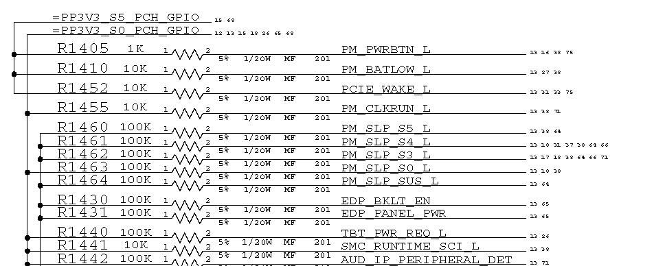
So the suspect chips are:
- R1410 open line or PP3V3_S5_PCH_GPIO not present on R1410
- Q3000 pulls down the voltage
- SMC u5000 pulls down the voltage (open drain function failed)
- CPU u0500 pulls down the voltage (faulty CPU, replacing CPU will be expensive)
Repair:
- Measure R1410 is 10K, ok. PP3V3_S5_PCH_GPIO is present on R1410 pin 1, 3.3V ok.
- Remove Q3000, PM_BATLOW_L is still 0.9V.
- Remove SMC u5000, connect a 3.3V external power to pin 1 of R1410, PM_BATLOW_L is 3.3V and ok now. This result means the SMC pulls down the voltage and the CPU is OK. We need a 3.3V external power for measurement as once we remove the SMC, we will not get the S5 rail PP3V3_S5 (PP3V3_S5 is controlled by SMC_PM_G2_EN output from SMC).
- back Q3000, get an SMC from a donor board, re-ball and solder back to the board. After that, the board is fully functional.
Case Study 3
MacBook Model: A1466 2015 820-000165
Fault Description: no power, very clean board no water damage, PP3V3_S5 present, PP5V_S3 missing.
Diagnosis: Trace PP5V_S3 enable signal P5VS4RS3_EN = 0V, not ok. It should be 3.3V. Trace P5VS4RS3_EN to R8179 and find out the PM_SLP_S4_L is missing (0V).

Analysis: Check the 11+1prerequisites, all are good except the PP3V3_SUS is low 0.1V. This power rail is from the 3.3V sus switch chip u8020.
Repair: Check u8020 input PP3V3_S5 is 3.3V, ok. Check u8020 enable signal P3V3SUS_EN is 3.3V, ok. So u8020 must be faulty. After replacing u8020, we have a fully functional board. The job was done in 10 minutes.
This is a very simple repair. If we don’t understand the PM_SLP_S4_L timing and use the guess-and-replace method, this repair could lead to a nightmare. We may replace the clock chip, the SMC, even the CPU and find out the board is still not working.
Case Study 4
MacBook Model: A1466 2013 820-3437
Fault Description: no power, water damage, PP3V3_S5 present, PP5V_S3 missing.
Diagnosis: All the11+1prerequisites are present. We use a multimeter to measure the PM_SLP_S4_L signal and the voltage is 0V. This is also a PM_SLP_S4_L missing logic board?
Analysis: Time to replace the PCH/CPU? NOT YET! If we cannot measure PM_SLP_S4_L on our multimeter, it doesn’t mean it does not exist. Below is the PM_SLP_S4_L signal shown on an oscilloscope.

PCH/CPU shoots out PM_SLP_S4_L at 800ms (timeline) after PPBUS_G3H had been created and stabilised. The PM_SLP_S4_L voltage is 3.3V, perfect. But it drops to 0V at 920ms. The PM_SLP_S4_L only exits for 120ms. This is why the multimeter did not pick it up.
So the suspect chips are:
- R1410 open line or PP3V3_S5_PCH_GPIO not present on R1410
- Q3000 pulls down the voltage
- SMC u5000 pulls down the voltage (open drain function failed)
- CPU u0500 pulls down the voltage (faulty CPU, replacing CPU will be expensive)
Repair: Check u8020 input PP3V3_S5 is 3.3V, ok. Check u8020 enable signal P3V3SUS_EN is 3.3V, ok. So u8020 must be faulty. After replacing u8020, we have a fully functional board. The job was done in 10 minutes.
Question: SPI_MLB_CS_L is S0 state signal and PM_SLP_S4_L is S4 state signal. How come the S0 signal affects the S4 signal? This question was asked in the last section of Louis Rossmann’s video “MacBook Air logic board repair PM_SLP_S4_L missing”?
In order to answer this question, we use a working 820-00165 board and a 4-channel oscilloscope. The 4-channel oscilloscope allows us to measure and compare 4 signals at a time and then stitch them together to get the whole picture of the power rails and control signals.
First of all, we need to make the SPI ROM chip not communicate with the CPU/PCH properly. This can be done by removing power to the SPI ROM U6100 or removing in-line signal resistors such as R6120, R6121 and so on. Here we choose to solder a jumper wire to short SPI_MLBROM_CS_L signal to the ground.
Then we connect our 4-channel oscilloscope to PM_SLP_S4_L and three other power rails or signals we want to measure. We assign the PM_SLP_S4_L signal as the trigger signal. We also set the trigger mode to single-pass mode instead of auto mode. All the measurement are conducted by connecting the charger without the battery. After repeating the measurement a few times, we get the following timeline char:
- We define the moment PPBUS_GH3 being created is 0 millisecond. The initial voltage of PPBUS_G3H is about 8.1V.
- At about 200ms, the SMC adjusts PPBUS_GH3 to about 8.6V.
- At about 350ms, PP3V3_S5 deep sleep power rail is created.
- At about 780ms, PM_RSMRST_L is present. The logic board is ready for “wakeup”.
- At about 788ms, PCH outputs PM_SLP_S4_L and PM_SLP_S3_L almost at the same time.
- At about 790ms, the memory power rail PP1V2_S3 is created. This is an S3 state power rail controlled by PM_SLP_S4_L.
- At about 791ms, the CPU/PCH front bus I/O power rail PP1V05_S0 is created. This is an S0 state power rail controlled by PM_SLP_S3_L.
- At about 800ms, ALL_SYS_PWRGD is present. All the S0 power rails are present and good except the CPU core rail.
- At about 805ms, CPU main power rail PPVCC_S0_CPU is created.
- At about 800ms, PPBUS_G3H drops from 8.6V to 7.8V momently and then comes back to normal. This is normal as all the S0 power rails are created at that time, resulting in a large amount of current is being dawned from PPBUS_G3H at the same time.
According to Intel’s CPU/PCH specification, when the PCH or the all-in-one CPU receives APWROK signal (Apple uses ALL_SYS_PWRGD as APWROK in this logic board), the CPU/PCH will use SPI bus to retrieve data from the SPI ROM. These data include CPU clock, system front bus clocks and other user-defined settings.
At about 915ms, the CPU/PCH still has not received the data from the SPI ROM, time is up.The CPU/PCH then withdraws the PM_SLP_S4_L signal and all the S3 and S0 power rails disappear. The CPU/PCH will output PM_SLP_S4_L again after waiting for 4250ms in the hope that the fault will be gone. If the fault is persistent, this process will repeat again and again.
Conclusion: The logic board is ALREADY in S0 state, even the CPU main power rail is present. But the CPU is not running the codes yet. The PM_SPL_S4_L signal only lasts for 127ms as the CPU/PCH fails to retrieve data from SPI ROM and then withdraw the signal. A normal multimeter is not fast enough to respond to the 127ms-length signal. If you have a fast-respond power supply, you may notice the current is jumping between 28mA and 33mA.
In pratics, we don’t use an oscilloscope to measure the signal unless all other simple methods have failed. In this situation, if you short the ALL_SYS_PWRGD signal to ground and the current drawn from the power supply increases and remains at about 128mA, the chances are you may have an SPI related issue. By shorting the ALL_SYS_PWRGD signal to ground, you prevent the CPU/PCH from withdrawing the PM_SLP_S4_L signal, so the S3 and S0 state power rails remain on. With a water-damaged logic board, pay attention to the corroded resistors, capacitors and traces (particular the cross-layer traces)
Note: If a logic analyzer is used in this project, the result figures will be more accurate. But the sequences in time are the same.
Next article:MacBook logic board power rails and ALL_SYS_PWRGD