
Where Stage 6 begins and ends
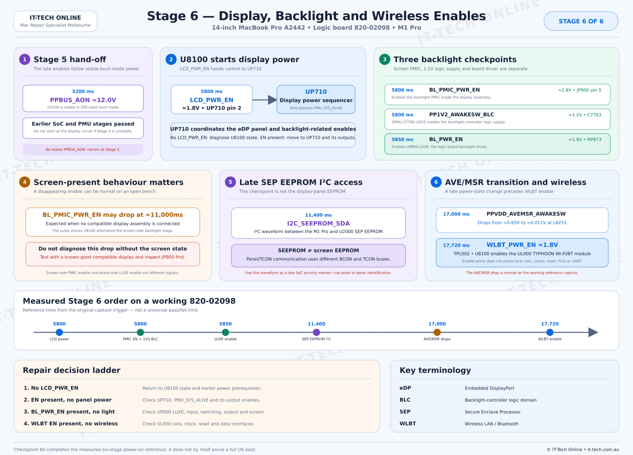
Stage 6 begins after the Stage 5 charger transition is complete and PPBUS_AON is stable at approximately 12.0V around 5200ms. The earlier PMU, SoC, NAND and USB-C stages must already be operating.
The final measured stage performs four main jobs:
- U8100 asserts LCD_PWR_EN and UP710 starts the display-power sequence.
- The screen-side backlight PMIC, 1.2V backlight logic and board-side UP800 LUXE driver are enabled.
- The M1 Pro accesses U2000 SEP EEPROM and U8100 performs a late AVE/MSR power-state transition.
- U8100 asserts WLBT_PWR_EN for the UL000 TYPHOON Wi-Fi/Bluetooth module.
Checkpoint 60 is the end of the measured six-stage reference. It confirms that the power sequence reached the wireless-enable stage, but it does not prove a successful macOS boot, panel image, backlight output or wireless enumeration.
Stage 6 sequence overview
Stage 6 prerequisites
A black screen is not enough reason to begin at UP710 or UP800. Confirm that the board reaches the final power stage before diagnosing the display circuits.
| Prerequisite | Expected condition | Why it matters |
|---|---|---|
| PPBUS_AON | Approximately 12.0V and stable in buck mode | Supplies the high-current board and backlight paths |
| PMU_SYS_ALIVE | High and stable | Required by UP710 and late PMU sequencing |
| PP3V8_AON and PP1V8_AON | Stable | Supply display sequencer and supporting logic |
| PP1V8_S2 and PP5V_S2_MAIN | Stable | Support U7700, UP800 and late interface logic |
| Stage 5 NAND and SoC activity | Sequence reaches checkpoints 45–53 | Shows that embedded-SMC and PMU startup progressed normally |
| Display and backlight rail resistance | No abnormal short | Prevents the sequencer or driver from shutting down |
LCD_PWR_EN and UP710 display-power sequencing
At approximately 5800ms, U8100 asserts LCD_PWR_EN to about 1.8V. UP710 pin 2 is the practical checkpoint. This is the first measured Stage 6 display enable.
LCD_PWR_EN is an instruction to UP710, not the finished panel supply. UP710 is the display power sequencer. It also requires PMU_SYS_ALIVE and the relevant always-on supplies. Its outputs coordinate the eDP-panel power, panel-related enables and backlight-related feed controls.
How to interpret LCD_PWR_EN
| Observation | Interpretation | Next checks |
|---|---|---|
| LCD_PWR_EN missing | U8100 has not requested the display stage | Earlier sequence, PMU state, U8100 output path |
| LCD_PWR_EN present but UP710 outputs absent | The hand-off reached UP710 but the sequencer did not progress | UP710 inputs, PMU_SYS_ALIVE, supplies, output load and sequencer IC |
| UP710 outputs present but no image | Panel power passed; move beyond the enable path | eDP link, TCON, connector, panel assembly and SoC display output |
Do not use LCD_PWR_EN alone as proof that the display panel is powered. Measure the UP710 outputs and the corresponding connector-side supplies.
Three different backlight checkpoints
The measured sequence contains three backlight-related checkpoints. They belong to different circuits and should not be combined into one “backlight enable.”
BL_PMIC_PWR_EN: screen-side backlight PMIC
BL_PMIC_PWR_EN rises to approximately 1.8V at about 5800ms and can be measured at JP900 pin 5. It travels through the BCON connector to enable the backlight PMIC inside the display assembly.
This signal does not enable UP800 on the logic board. A fault in the display cable, JP900, screen-side PMIC or compatible-panel detection can affect this path independently of the board-side backlight converter.
PP1V2_AWAKESW_BLC: backlight logic supply
At approximately 5800ms, SPMU U7700 LDO3 creates about 1.2V PP1V2_AWAKESW_BLC. C7763 is the recorded test point. The rail supplies the backlight-controller logic domain and is also routed through the BCON interface.
If BL_PMIC_PWR_EN is present but PP1V2_AWAKESW_BLC is missing, check U7700 LDO3 input, its local capacitors, C7763, the BCON load and resistance to ground. Do not replace the display solely because this board-generated rail is absent.
BL_PWR_EN: logic-board UP800 LUXE enable
BL_PWR_EN rises to approximately 1.8V at about 5850ms and can be measured at RP873. This signal enables UP800 LUXE, the logic-board backlight driver.
UP800 uses the PPBUS_AON_LUXE_ISNS input path, support rails and external switching components to create PPVOUT_LUXE for the display assembly. The circuit includes the controller, MOSFET stages, LP800, current-sense paths, filtering and the output route through JP900.
If BL_PWR_EN is present but PPVOUT_LUXE is missing, check the UP800 input and support rails, resistance on PPVOUT_LUXE, the MOSFET stages, LP800, sense components and the screen-side load. Use an oscilloscope for switching diagnosis.
Expected behaviour when no screen is connected
The working reference records that BL_PMIC_PWR_EN may fall at approximately 11,000ms when no screen is connected. This can be a deliberate response to the missing display assembly rather than a defective U8100 output.
Bench-testing rule: record whether BL_PMIC_PWR_EN rises first. A pulse followed by a drop with no compatible screen connected has a different meaning from a signal that never rises.
Before condemning the board:
- Inspect JP900 and the display cable under magnification.
- Test with a known-good compatible display assembly.
- Confirm BL_PMIC_PWR_EN, PP1V2_AWAKESW_BLC and BL_PWR_EN separately.
- Check whether PPVOUT_LUXE appears before shutdown.
- Compare the timing with the screen connected and disconnected.
UP800 LUXE does not create the panel image
UP800 provides backlight power. It does not create the eDP image data. A Mac can therefore have:
- Image but no backlight: eDP and TCON are operating, but the backlight power or enable path has failed.
- Backlight but no image: backlight circuits are active, but the eDP, TCON, panel-power or data path has failed.
- No image and no backlight: an earlier shared display-power condition, connector, screen assembly or complete board-sequence fault may exist.
Use a flashlight test, known-good display and external-display behaviour as supporting evidence, but confirm the actual rails and signals before selecting a component to replace.
Checkpoint 58: I2C_SEEPROM_SDA is not panel identification
At approximately 11,400ms, the measured timeline records I2C_SEEPROM_SDA activity. The schematic connects this bus between the M1 Pro and U2000, which is labelled SEP EEPROM.
SEP refers to the Secure Enclave Processor. U2000 is therefore not the display-panel EEPROM, and I2C_SEEPROM_SDA should not be presented as direct proof that the panel or TCON has been identified.
The panel and backlight assembly use separate BCON, TCON, SPI and I²C-related paths. In this Stage 6 sequence, the U2000 waveform is valuable as a late SoC-activity checkpoint: the M1 Pro has continued executing well beyond the first display enables.
How to measure the SEEPROM bus
Use an oscilloscope or logic analyser to confirm both SDA and SCL activity. A multimeter can detect a stuck-low line or missing pull-up but cannot prove valid I²C data. Verify the U2000 supply and bus pull-ups before treating the EEPROM as defective.
PPVDD_AVEMSR_AWAKESW late transition
PPVDD_AVEMSR_AWAKESW was created in Stage 5 at approximately 4700ms. On this working capture, the rail later falls from about 0.65V to approximately 0.011V at 17,000ms. L8253 is the practical checkpoint.
The drop is a programmed late power-state transition in this reference capture, not an automatic sign of rail collapse. Record whether the rail first rises correctly and whether the board reaches the surrounding checkpoints.
Because timing can change with boot state and connected hardware, use the behaviour as a sequence marker rather than a universal voltage deadline. An abnormal rail that never rises, collapses much earlier or drags other supplies down should still be investigated at U8100 BUCK5, L8253 and the AVE/MSR load.
WLBT_PWR_EN and the TYPHOON wireless module
At approximately 17,720ms, U8100 asserts WLBT_PWR_EN to about 1.8V. TPL002 is the recorded test point. The signal enables UL000, identified by the schematic codename TYPHOON, which provides Wi-Fi and Bluetooth functions.
WLBT_PWR_EN proves that U8100 reached the wireless-enable stage. It does not prove that UL000 has every required condition. The module also relies on:
- PP3V8_AON_WLBT_ISNS and PP1V8_S2 supply domains
- PMU_CLK32K_WLBT reference clock
- SPMI_WLBT_CLK and SPMI_WLBT_DATA management communication
- Wireless reset and wake control
- PCIe communication for Wi-Fi
- UART and low-power interfaces for Bluetooth
If WLBT_PWR_EN is missing, remain with U8100 state and the earlier sequence. If the enable is present but Wi-Fi and Bluetooth are absent, move to UL000 supplies, clock, reset, management traffic and data interfaces.
Complete measured Stage 6 order
| Step | Time | Signal or rail | Expected | Test point | Meaning | If missing or abnormal |
|---|---|---|---|---|---|---|
| 54 | 5800ms | LCD_PWR_EN | ≈1.8V | UP710 pin 2 | U8100 requests the display-power sequence | No display enable; return to U8100 and earlier stages |
| 55 | 5800ms | BL_PMIC_PWR_EN | ≈1.8V | JP900 pin 5 | Enables the backlight PMIC inside the screen | Screen-side backlight PMIC not enabled; a later drop can be normal with no screen |
| 56 | 5800ms | PP1V2_AWAKESW_BLC | ≈1.2V | C7763 | U7700 LDO3 creates the backlight logic rail | Check U7700, input supply and BLC load |
| 57 | 5850ms | BL_PWR_EN | ≈1.8V | RP873 | Enables the logic-board UP800 LUXE driver | No board-side backlight-driver enable |
| 58 | 11,400ms | I2C_SEEPROM_SDA | I²C waveform | U2000 bus | M1 Pro communicates with the SEP EEPROM | Late SoC/SEP-EEPROM communication issue; not direct panel identification |
| 59 | 17,000ms | PPVDD_AVEMSR_AWAKESW | Drops to ≈0.011V after previously reaching ≈0.65V | L8253 | Working-reference late AVE/MSR power-state transition | Compare complete rail timing and U8100 BUCK5 behaviour |
| 60 | 17,720ms | WLBT_PWR_EN | ≈1.8V | TPL002 | U8100 enables the UL000 Wi-Fi/Bluetooth module | Wireless-enable stage missing |
Signal and rail ownership
| Checkpoint | Primary owner | Immediate destination | First diagnostic boundary |
|---|---|---|---|
| LCD_PWR_EN | U8100 MPMU | UP710 | Missing signal = U8100/sequence; present signal = UP710/output path |
| BL_PMIC_PWR_EN | U8100 MPMU | Display-assembly backlight PMIC through JP900 | Separate screen-side enable |
| PP1V2_AWAKESW_BLC | U7700 SPMU LDO3 | Backlight-controller logic and BCON | Board-generated 1.2V supply |
| BL_PWR_EN | U8100 MPMU | UP800 LUXE through RP873 | Separate logic-board backlight-driver enable |
| I2C_SEEPROM_SDA | M1 Pro SoC | U2000 SEP EEPROM | Late SoC communication, not panel EEPROM |
| PPVDD_AVEMSR_AWAKESW | U8100 BUCK5 | AVE/MSR SoC domain | Capture-specific late deassertion |
| WLBT_PWR_EN | U8100 MPMU | UL000 TYPHOON | Enable present = continue inside wireless module path |
Recommended diagnostic order
- Confirm Stage 5 completes and PPBUS_AON is stable near 12.0V.
- Record whether a compatible display is connected.
- Measure LCD_PWR_EN at UP710 pin 2.
- If LCD_PWR_EN is present, measure UP710 supplies and output enables.
- Measure BL_PMIC_PWR_EN at JP900 pin 5 and record whether it pulses or remains high.
- Measure PP1V2_AWAKESW_BLC at C7763.
- Measure BL_PWR_EN at RP873.
- If BL_PWR_EN is present, check UP800 supplies, PPVOUT_LUXE resistance and switching activity.
- Inspect JP900, the display cable and screen assembly.
- Capture I2C_SEEPROM SDA and SCL as a late SoC checkpoint, without confusing it with panel identification.
- Record the complete PPVDD_AVEMSR_AWAKESW rise-and-fall behaviour at L8253.
- Measure WLBT_PWR_EN at TPL002, then continue into UL000 supplies, clocks and interfaces if it is present.
Common Stage 6 fault patterns
| What you observe | Most useful interpretation |
|---|---|
| Stage 5 passes but LCD_PWR_EN never rises | U8100 has not entered the display-enable state or its output path is faulty |
| LCD_PWR_EN present but UP710 outputs absent | UP710 supply, PMU_SYS_ALIVE, sequencer or downstream-load fault |
| BL_PMIC_PWR_EN pulses then falls with no screen connected | Expected working-reference behaviour; retest with a compatible display |
| BL_PMIC_PWR_EN present but PP1V2_AWAKESW_BLC missing | U7700 LDO3, C7763 or 1.2V BLC load fault |
| BL_PWR_EN missing while earlier display enables are present | U8100 has not released the board-side LUXE stage |
| BL_PWR_EN present but PPVOUT_LUXE missing | UP800, its input/support rails, MOSFETs, LP800, sense path or output load |
| Panel image visible with flashlight but no illumination | eDP image path works; diagnose backlight enable and power conversion |
| Backlight present but no image | Diagnose panel power, eDP, TCON, connector and data path rather than UP800 output |
| I2C_SEEPROM missing | U2000 SEP-EEPROM bus or late SoC activity issue—not direct evidence of a screen EEPROM fault |
| WLBT_PWR_EN present but Wi-Fi and Bluetooth are absent | UL000 local supply, clock, reset, SPMI, PCIe or UART problem |
Terminology used in this guide
| Term | Full name or meaning | Function in Stage 6 |
|---|---|---|
| LCD | Liquid-Crystal Display | Display-related enable naming used by the board |
| eDP | Embedded DisplayPort | Digital image link between the SoC and internal display |
| PMIC | Power Management Integrated Circuit | Screen-side backlight power controller |
| BLC | Backlight-controller logic domain | 1.2V awake supply created by U7700 LDO3 |
| LUXE | Apple functional codename | UP800 logic-board backlight driver |
| BCON | Board/display backlight connector naming | JP900 interface to the display assembly |
| TCON | Timing Controller | Controls the display panel timing and data operation |
| SEP | Secure Enclave Processor | Security subsystem associated with U2000 SEP EEPROM |
| EEPROM | Electrically Erasable Programmable Read-Only Memory | Small non-volatile configuration storage |
| I²C | Inter-Integrated Circuit | Two-wire serial communication using SDA and SCL |
| WLBT | Wireless LAN / Bluetooth | Wireless-module enable naming |
| WLAN | Wireless Local Area Network | Wi-Fi networking function |
| TYPHOON | Apple functional codename | UL000 Wi-Fi/Bluetooth module |
| PCIe | Peripheral Component Interconnect Express | High-speed Wi-Fi data interface |
| UART | Universal Asynchronous Receiver/Transmitter | Serial interface used by Bluetooth-related control/data |
| SPMI | System Power Management Interface | Management communication with the wireless module |
| _EN suffix | Enable signal | Requests the associated power or functional stage |
Frequently asked questions
Does LCD_PWR_EN prove that the panel has power?
No. LCD_PWR_EN proves that U8100 requested the stage. UP710 must still receive its prerequisites and create the downstream display enables.
Are BL_PMIC_PWR_EN and BL_PWR_EN the same signal?
No. BL_PMIC_PWR_EN enables the PMIC inside the screen through JP900. BL_PWR_EN enables UP800 LUXE on the logic board.
Is BL_PMIC_PWR_EN faulty if it drops after about 11 seconds?
Not necessarily. The working reference shows that it can drop when no screen is connected. Record whether it rose first and repeat the test with a known-good compatible display.
Does I2C_SEEPROM_SDA identify the display?
No. The schematic connects it to U2000 SEP EEPROM. Display/TCON communication uses different buses.
Why does PPVDD_AVEMSR_AWAKESW fall late in the sequence?
On the working capture it is a later U8100 power-state transition. Interpret the complete waveform and surrounding checkpoints rather than treating the low final value as an immediate fault.
Does WLBT_PWR_EN prove that Wi-Fi and Bluetooth work?
No. It proves only that U8100 enabled the module. UL000 still needs supplies, clocks, reset, management traffic and functional PCIe/UART interfaces.
Measurement and safety notes
Use DC voltage measurement for LCD_PWR_EN, BL_PMIC_PWR_EN, PP1V2_AWAKESW_BLC, BL_PWR_EN, PPVDD_AVEMSR_AWAKESW and WLBT_PWR_EN. Use an oscilloscope or logic analyser for I²C, switching nodes, clock signals and short-lived enables.
Disconnect all power before resistance, continuity or diode-mode testing. The backlight converter can produce a voltage substantially higher than PPBUS_AON. Use appropriately rated probes and avoid touching PPVOUT_LUXE while powered.
Never connect a grounded oscilloscope clip to an unidentified floating switch node. Avoid probing JP900 with a loose or oversized tip because adjacent high-voltage backlight and low-voltage logic pins can be shorted together.
Do not inject voltage into display, TCON, SEP-EEPROM, WLBT control or SoC rails. Test with a known-good compatible display before replacing a logic-board controller based only on an absent image.
Completing the six-stage diagnostic sequence
When WLBT_PWR_EN appears at checkpoint 60, the measured board has completed all six reference stages:
- USB-C input and PPBUS_AON boost
- MPMU, SPMU, always-on and S2 rails
- Viper, MONACO and SoC awake rails
- Embedded SMC and SoC-ROM startup
- NAND power and USB-C 20V negotiation
- Display, backlight and wireless enables
If all 60 checkpoints pass but the Mac still does not boot correctly, move beyond the power-on sequence into firmware, storage communication, SoC execution, eDP image data, peripheral enumeration or operating-system diagnosis. Return to the complete A2442 820-02098 M1 Pro power-on sequence to review the last confirmed stage.