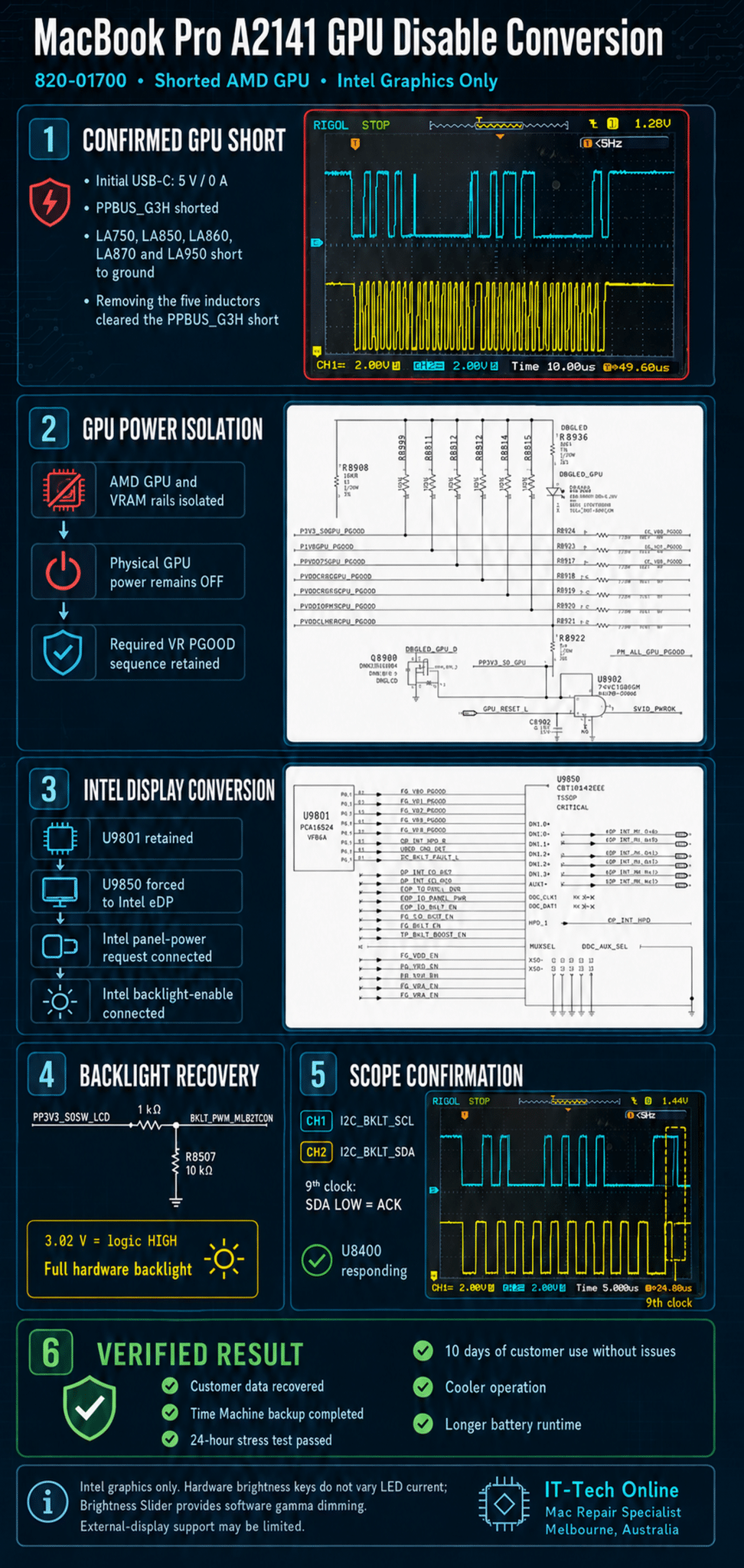
MacBook Pro A2141 820-01700 GPU Disable Conversion
Shorted AMD GPU and VRAM isolated – permanent Intel integrated graphics conversion
INTRODUCTION
A failed dedicated GPU does not automatically mean that a MacBook Pro is beyond repair. It also does not automatically mean that the customer’s data has been destroyed.
This 2019 16-inch MacBook Pro had several AMD GPU and video-memory power rails shorted to ground. The short prevented normal USB-C power negotiation and made the Mac appear completely dead.
The customer had already been told that the GPU was damaged, the Mac could not be repaired and all the data was gone. Our first objective was to protect and recover the data. We then investigated whether the Mac could be permanently converted to Intel integrated graphics.
Unlike older 2011–2015 MacBook Pro models, the 820-01700 does not use a conventional GMUX that can simply be removed and bypassed. GPU sequencing, eDP switching, panel power, backlight enable and brightness control are divided between several separate circuits.
The conversion required us to:
• Isolate the shorted AMD GPU and VRAM power domains
• Retain the expected GPU power-good sequence
• Force the high-speed eDP multiplexer to Intel graphics
• Recreate the Intel panel-power path
• Recreate the Intel backlight-enable path
• Confirm backlight-controller I2C communication
• Restore full hardware backlight through the display TCON input
IMPORTANT
This is an advanced component-level logic-board modification. The controller and load sides of every signal must be confirmed from the boardview and schematic before installing jumpers.
The procedure should not be applied to another logic-board revision without checking its circuit design.
Fault Description
Device: 16-inch MacBook Pro 2019
Model: A2141
Logic board: 820-01700
Customer area: 3806
Customer complaint: Mac suddenly died; no power; no water damage reported
Previous diagnosis: Dedicated GPU damaged; Mac and data declared unrecoverable
Initial USB-C reading: 5 V, 0 A
Primary electrical fault: PPBUS_G3H shorted through failed AMD GPU and VRAM power domains
Customer decision: Accepted a permanent Intel-integrated-graphics-only conversion
Initial Measurements
The initial USB-C reading of 5 V and 0 A showed that the board was not progressing into normal high-voltage USB-C negotiation.
An inductor survey identified PPBUS_G3H as shorted. The following GPU-related inductor outputs were also shorted to ground:
• LA750
• LA850
• LA860
• LA870
• LA950
All five inductors were removed to isolate the failed AMD GPU and video-memory loads.
After the five loads were disconnected, PPBUS_G3H was no longer shorted. This was the decisive diagnostic result: the fault was contained within the dedicated GPU and VRAM subsystem rather than the CPU, onboard SSD or customer-data path.
The failed AMD subsystem had prevented the entire Mac from powering on, but the customer’s data was not inherently lost.
Why the 820-01700 Is Different From Older GMUX Boards
On many older MacBook Pro logic boards, the GMUX handles:
• Integrated and dedicated GPU selection
• LCD panel power
• Backlight enable
• Hardware brightness PWM
• Display switching during sleep and wake
Removing the GMUX and routing the Intel signals to the LCD connector can be sufficient on those designs.
The 820-01700 divides these functions between U9801, U9850, the CPU/PCH display signals, the display TCON and the U8400 backlight driver.
U9801 is an I2C GPIO expander. It participates in GPU voltage-regulator sequencing, power-good monitoring, panel-power control and backlight control.
U9850 is the high-speed 2:1 eDP multiplexer that selects either the AMD or Intel eDP source for the internal display.
U8400, marked LP8548B1, is the logic-board LED backlight driver. It receives backlight enable through EDP_BKLT_EN and brightness programming through the I2C_BKLT bus.
J8500 carries the eDP lanes, panel supply, TCON control buses and BKLT_PWM_MLB2TCON signal to the display assembly.
Circuit Logic: GPU Power Sequencing
Schematic page 116 shows five U9801-controlled GPU voltage-regulator stages.
Their enable signals leave U9801 as EG_VR0_EN through EG_VR4_EN. The signals pass through RB900–RB904 toward the physical GPU regulators.
Corresponding PGOOD signals return to U9801:
VR0
Enable path: EG_VR0_EN → RB900 → P3V3GPU_EN
Physical confirmation: P3V3_S0GPU_PGOOD
Return path: RB924 → EG_VR0_PGOOD
VR1
Enable path: EG_VR1_EN → RB901 → P1V8GPU_EN
Physical confirmation: P1V8GPU_PGOOD
Return path: RB923 → EG_VR1_PGOOD
VR2
Enable path: EG_VR2_EN → RB902 → PVDD075GPU_EN
Physical confirmation: PVDD075GPU_PGOOD
Return path: RB917 → EG_VR2_PGOOD
VR3
Enable path: EG_VR3_EN → RB903 → PVDDCOREGPU_EN
Physical confirmation: GPU core and SOC PGOOD signals
Return path: RB918 and RB919 → EG_VR3_PGOOD
VR4
Enable path: EG_VR4_EN → RB904 → PVDDMEMGPU_EN
Physical confirmation: GPU memory PGOOD signals
Return path: RB920 and RB921 → EG_VR4_PGOOD
The schematic specifies that EG_VR4_PGOOD must be the final PGOOD in the sequence.
For an Intel-only conversion, the physical AMD power loads must remain disconnected while U9801 still receives the expected logical PGOOD progression.
The conversion therefore retained the required simulated EG_VR0_PGOOD through EG_VR4_PGOOD sequence without allowing the failed GPU and VRAM rails to turn on.
IMPORTANT ISOLATION RULE
A simulated PGOOD level must never be connected to a still-connected shorted regulator output. Confirm the controller side and load side in the boardview before installing any PGOOD jumper.

Circuit Logic: U9801 and U9850
U9801 is not merely an older-style graphics multiplexer. It is an I2C GPIO expander that performs several GPU-sequencing and display-control functions.
Removing it permanently would also remove functions still required for Intel-only operation. U9801 was therefore retained in the final conversion, with only the necessary outputs overridden.
U9850 is the actual high-speed 2:1 eDP multiplexer.
It receives:
• Four AMD eDP lanes and AUX signals
• Four Intel eDP lanes and AUX signals
• A GPU selection input controlled through EDP_MUXSEL_OVR and R9819
U9850 sends the selected eDP source to the internal display connector.
Keeping U9850 in circuit avoids manually wiring four controlled-impedance eDP lane pairs. Only its selection state needs to be overridden.

Workshop Conversion Sequence
Removing LA750, LA850, LA860, LA870 and LA950 isolated the shorted AMD GPU and VRAM loads and cleared the PPBUS_G3H short.
However, removing the output inductors alone is not sufficient for the permanent conversion. Every AMD regulator enable must also be disconnected, and the genuine regulator PGOOD returns must be isolated before simulated PGOOD signals are created.
The complete GPU enable and PGOOD network is shown on schematic page 116.
1. Isolate the Shorted AMD GPU and VRAM Loads
The following inductors were shorted on their GPU or VRAM load sides:
• LA750
• LA850
• LA860
• LA870
• LA950
All five inductors were removed.
After their removal:
• The PPBUS_G3H short cleared
• The shorted GPU and VRAM loads were isolated
• PPBUS_G3H returned to a normal condition
• The CPU, onboard SSD and customer-data circuits were no longer being held down by the failed GPU subsystem
2. Retain U9801 as the GPU Sequence Controller
U9801 must remain in circuit because it controls more than the dedicated GPU.
Its functions include:
• EG_VR0–EG_VR4 enable sequencing
• GPU PGOOD monitoring
• PM_ALL_GPU_PGOOD generation
• Display-control signals
• Panel-power control
• Backlight-control signals
• I2C display management
The conversion therefore allows U9801 to produce its normal GPU enable sequence, but prevents those enables from reaching the physical AMD voltage regulators.
3. Disable Every Physical AMD GPU Rail
Remove the five 0 Ω series enable resistors between U9801 and the AMD GPU voltage regulators.
| Remove | U9801-side signal | Disabled regulator or rail |
|---|---|---|
| RB900 | EG_VR0_EN | PP3V3_S0_GPU |
| RB901 | EG_VR1_EN | PP1V8_S0_GPU |
| RB902 | EG_VR2_EN | PP0V75_S0_GPU |
| RB903 | EG_VR3_EN | PPGFX_S0_GPU and PPSOC_S0_GPU |
| RB904 | EG_VR4_EN | GPU memory rails |
According to the schematic:
• Pin 1 is the U9801 side
• Pin 2 is the physical regulator side
• RB900–RB904 are all 0 Ω series resistors
After their removal:
• U9801 can still produce its normal EG_VR0_EN through EG_VR4_EN sequence
• None of the enable signals reaches the AMD GPU regulators
• The GPU regulators remain disabled
• Every physical AMD GPU output rail should remain at 0 V
Confirm that the regulator-side pads remain low during startup before continuing.
4. Isolate the Genuine Regulator PGOOD Signals
The real PGOOD signals from the disabled GPU regulators must not remain connected to the U9801 PGOOD inputs.
Remove the following components:
| Remove | U9801 input isolated |
| RB924 | EG_VR0_PGOOD |
| RB923 | EG_VR1_PGOOD |
| RB917 | EG_VR2_PGOOD |
| RB918 and RB919 | EG_VR3_PGOOD |
| RB920 and RB921 | EG_VR4_PGOOD |
RB918 and RB919
The pin-2 ends of RB918 and RB919 join at the EG_VR3_PGOOD input to U9801.
Their regulator-source sides must remain separate. Do not connect the original GPU-core and GPU-SOC PGOOD outputs together.
RB920 and RB921
The pin-2 ends of RB920 and RB921 join at the EG_VR4_PGOOD input to U9801.
Their regulator-source sides must also remain separate. Do not connect the original GPU-memory PGOOD outputs together.
IMPORTANT
Only the U9801 input-side nodes are used for the simulated PGOOD signals.
The original regulator-source sides must remain isolated because the physical GPU regulators and output rails will be disabled.
5. Make Each Fake PGOOD Follow Its Corresponding Enable
Do not pull every GPU PGOOD signal permanently to 3.3 V.
Instead, make each U9801 PGOOD input follow its corresponding U9801 enable output through an approximately 10 kΩ resistor.
Install the following five resistive jumpers:
| Fake PGOOD | From | To |
| Fake VR0 | RB900 pin 1 | RB924 pin 2 |
| Fake VR1 | RB901 pin 1 | RB923 pin 2 |
| Fake VR2 | RB902 pin 1 | RB917 pin 2 |
| Fake VR3 | RB903 pin 1 | Joined RB918/RB919 pin-2 node |
| Fake VR4 | RB904 pin 1 | Joined RB920/RB921 pin-2 node |
Each jumper should use approximately 10 kΩ.
The operating principle is:
U9801 asserts EG_VR0_EN.
The signal passes through the new 10 kΩ resistor.
U9801 then reads EG_VR0_PGOOD as high.
The same arrangement is repeated for VR1, VR2, VR3 and VR4.
Why Sequenced Fake PGOOD Is Better Than Permanent Pull-Ups
This arrangement preserves the basic timing relationship between each enable and its corresponding PGOOD input:
• PGOOD remains low before the sequence begins
• PGOOD rises only after its corresponding enable rises
• PGOOD falls when its corresponding enable is removed
• Each PGOOD follows the correct U9801 sequencing stage
• The arrangement more closely resembles normal regulator behaviour
• U9801 can complete its normal VR0-to-VR4 sequence without powering the failed AMD GPU
The existing 47 kΩ enable pull-down resistors R9820–R9824 should remain fitted.
These pull-downs hold both the enable outputs and the simulated PGOOD inputs low while U9801 is in reset or inactive.
Leave RB922 Installed
Do not remove RB922.
RB922 connects:
EG_VR4_PGOOD → PM_ALL_GPU_PGOOD
VR4 is the final stage of the GPU sequence.
When U9801 asserts EG_VR4_EN:
- RB904 pin 1 rises
- The new 10 kΩ jumper raises the joined RB920/RB921 pin-2 node
- U9801 reads EG_VR4_PGOOD as high
- RB922 passes the completed state to PM_ALL_GPU_PGOOD
- The system receives confirmation that the complete GPU power sequence has finished
This allows PM_ALL_GPU_PGOOD to be generated without turning on any of the physical AMD GPU regulators.
Measurements After Completing the Modification
Before proceeding with the display conversion, confirm the following:
| Test | Expected result |
| RB900–RB904 pin 1 | Normal sequential U9801 enable activity |
| RB900–RB904 pin 2 | Remains low; signals do not reach regulators |
| Physical AMD GPU rails | 0 V |
| RB924 pin 2 | Follows RB900 pin 1 through 10 kΩ |
| RB923 pin 2 | Follows RB901 pin 1 through 10 kΩ |
| RB917 pin 2 | Follows RB902 pin 1 through 10 kΩ |
| Joined RB918/RB919 pin-2 node | Follows RB903 pin 1 through 10 kΩ |
| Joined RB920/RB921 pin-2 node | Follows RB904 pin 1 through 10 kΩ |
| PM_ALL_GPU_PGOOD | Appears after the VR4 stage |
| PPBUS_G3H | No longer shorted |
| GPU and VRAM regulator outputs | Remain at 0 V |
If any physical GPU output rail appears, stop and check RB900–RB904 isolation before continuing.
6. Connect Intel Panel Power and Backlight Enable
After the physical GPU rails were disabled and the simulated PGOOD sequence was working, the Intel display-control requests were connected to the final display paths:
EDP_IG_PANEL_PWR → EDP_PANEL_PWR_EN
EDP_IG_BKLT_EN → EDP_BKLT_EN
This produced an Intel-driven image with a dim Apple logo.
PPVOUT_S0_LCDBKLT measured approximately 54.3 V, confirming that the panel supply, backlight boost converter and LED strings were operating.
7. Force U9850 to the Intel eDP Source
U9801 was retained for its required control functions.
The U9801 side of the R9819 selection path was isolated, and the U9850 mux-side input was forced to a definite 3.3 V state.
This permanently selected Intel eDP while keeping the high-speed eDP lanes routed through U9850.
8. Confirm I2C Backlight Communication
Schematic page 81 shows U8400/LP8548B1 on the logic board.
EDP_BKLT_EN reaches U8400’s enable input through R8442. The display TCON communicates with U8400 through:
• I2C_BKLT_SCL
• I2C_BKLT_SDA
The converted board was compared with a known-good board.
At a wide timebase, both SCL and SDA showed active communication. Captures at 5 µs/div and 2 µs/div allowed individual byte frames and the ninth clock to be inspected.
During the ninth SCL-high period, SDA was low. This is a valid I2C ACK and confirms that U8400 was alive and acknowledging the TCON transaction.
The ACK ruled out:
• An open SCL or SDA trace
• U8400 being unpowered
• A continuously NACKing backlight controller
• A completely inactive TCON-to-backlight communication path
The ACK does not prove that the brightness value was identical to the value used in the original AMD-GPU configuration. It only confirms that the controller received and acknowledged the transaction.


9.BKLT_PWM_MLB2TCON Backlight Recovery
Schematic page 82 shows BKLT_PWM_MLB2TCON connected to J8500 pin 16.
In the normal production configuration:
• R8507 is fitted as a 10 kΩ pull-down to ground
• R8508 is marked NOSTUFF
• The optional R8508 position connects the node to PP3V3_S0SW_LCD
A 1 kΩ resistor was installed in the R8508 pull-up position. R8507 remained fitted.
The completed circuit was:
PP3V3_S0SW_LCD
↓
R8508 position fitted with 1 kΩ
↓
BKLT_PWM_MLB2TCON
↓
J8500 pin 16 and the display TCON
↓
Existing R8507 10 kΩ pull-down
↓
Ground
The resulting BKLT_PWM_MLB2TCON voltage was approximately 3.02 V.
The backlight immediately changed from dim to full physical brightness.
Testing the node at both 3.02 V and 3.3 V produced no brightness difference. This confirmed that the display TCON interprets 3.02 V as a valid digital high rather than an analogue brightness setting.
The 1 kΩ pull-up was retained because it:
• Produces a reliable logic-high level
• Limits current if the TCON ever drives the signal low
• Uses the switched PP3V3_S0SW_LCD supply
• Automatically disappears when LCD power switches off
BKLT_PWM_MLB2TCON does not connect directly to the logic-board U8400 backlight driver.
It is an input to the display TCON. The TCON interprets this high state and communicates with U8400 through I2C_BKLT.

Final Modification Summary
| Stage | Final modification | Confirmed result |
|---|---|---|
| GPU load isolation | Removed LA750, LA850, LA860, LA870 and LA950 | PPBUS_G3H short cleared |
| GPU regulator enables | Removed 0 Ω resistors RB900–RB904, preventing EG_VR0_EN through EG_VR4_EN from reaching the physical AMD regulators | U9801 continues its normal sequence, but none of the AMD regulator enables reaches the GPU power circuits |
| Real GPU PGOOD isolation | Removed RB924, RB923, RB917, RB918, RB919, RB920 and RB921 | The disabled regulators and their genuine PGOOD outputs are separated from U9801’s PGOOD inputs |
| Sequenced fake PGOOD | Added five approximately 10 kΩ jumpers from RB900–RB904 pin 1 to their corresponding U9801 PGOOD nodes | Each simulated PGOOD rises and falls with its matching U9801 enable |
| Final GPU PGOOD | Left RB922 fitted between EG_VR4_PGOOD and PM_ALL_GPU_PGOOD | The final VR4 stage generates PM_ALL_GPU_PGOOD after the simulated GPU sequence completes |
| Physical GPU rails | Confirmed that all AMD GPU and VRAM regulator outputs remained at 0 V | The failed AMD GPU and VRAM subsystem remains permanently unpowered |
| GPU logical sequence | Retained the required EG_VR0–EG_VR4 PGOOD progression using the five sequenced fake PGOOD returns | System power and display sequencing completes without powering the failed GPU |
| eDP selection | Isolated the U9801 control side of the R9819 selection path and forced U9850 to Intel | Intel eDP is permanently routed to the internal display |
| Panel power | Connected EDP_IG_PANEL_PWR to the EDP_PANEL_PWR_EN path | LCD panel power is sequenced correctly |
| Backlight enable | Connected EDP_IG_BKLT_EN to the EDP_BKLT_EN path | U8400 is enabled with the Intel display timing |
| Backlight fallback | Installed a 1 kΩ pull-up at R8508 while retaining the existing R8507 10 kΩ pull-down | BKLT_PWM_MLB2TCON measures approximately 3.02 V and full hardware backlight is restored |
| User brightness | Installed and configured Brightness Slider | Visible brightness can be adjusted using software gamma dimming |
Brightness-Control Limitation
The original Touch Bar brightness controls do not vary the physical LED current after this conversion.
The LED backlight operates at full electrical brightness. The Brightness Slider application changes the displayed image using software or gamma dimming.
Gamma dimming changes the pixel levels rather than reducing LED backlight power.
At very low software-brightness settings, the user may notice reduced contrast or lost shadow detail. Brightness Slider should be configured to start automatically at login.
Despite the backlight operating at full electrical power, the converted Mac ran cooler and achieved longer battery runtime. The disabled AMD GPU, VRAM, voltage regulators and their associated power losses consumed considerably more energy than the full-brightness backlight.
Testing and Verified Result
The customer’s data was backed up before extended stress testing.
The converted Mac passed:
• Complete Time Machine backup
• 24-hour stress test
• Repeated cold boots
• Repeated restarts and shutdowns
• Sleep and wake testing
• Lid close and reopen testing
• Internal-display stability testing
• Backlight shutdown during sleep
• Intel graphics and high-resolution video playback
• Keyboard, trackpad and Touch Bar testing
• Wi-Fi, audio and camera testing
• USB-C port testing
• Battery charging and battery-only operation
• Thermal and fan-response testing
The customer subsequently used the Mac for ten days without any reported problems.
The system operated cooler and achieved longer battery runtime because the dedicated AMD GPU and VRAM subsystem no longer consumed power or generated heat.
Advantages and Limitations
Advantages
• Customer data recovered and backed up
• Mac remains usable for normal everyday work
• Lower operating temperature
• Lower cooling-system load
• Longer observed battery runtime
• Failed GPU and VRAM rails remain permanently isolated
• No heat-generating GPU reflow or temporary repair
Limitations
• No AMD graphics acceleration
• Reduced graphics performance
• Hardware brightness controls do not reduce LED current
• Software gamma dimming is required
• Some external-display functions may be unavailable
• The conversion should be treated as permanent
Key Lesson
A shorted dedicated GPU can make an A2141 MacBook Pro appear completely dead while the CPU, onboard SSD and customer data remain recoverable.
A failed dedicated GPU does not automatically mean a failed SSD or lost customer data.
On the 820-01700, a successful Intel-only conversion requires GPU power sequencing, eDP source selection, panel power, backlight enable and TCON brightness control to be treated as separate systems.
Solving only one of these systems is not sufficient.
Final Fix
The failed AMD GPU and VRAM power domains were isolated by removing LA750, LA850, LA860, LA870 and LA950.
The required VR PGOOD sequence was retained without powering the failed GPU. U9801 remained in circuit for its necessary sequencing and display-control functions.
U9850 was permanently forced to the Intel eDP source. The Intel panel-power and backlight-enable requests were connected to their final control paths.
A 1 kΩ pull-up fitted at R8508 held BKLT_PWM_MLB2TCON at approximately 3.02 V and restored full hardware backlight.
Brightness Slider provides software gamma dimming for day-to-day brightness adjustment.
The customer’s data was recovered, a complete Time Machine backup was created and the previously unusable Mac returned to service using Intel integrated graphics.
Case Summary
Before repair
• USB-C meter remained at 5 V and 0 A
• PPBUS_G3H was shorted
• Five AMD GPU and VRAM rails were shorted to ground
• The Mac was unusable
• The customer had been told that the data was gone
After conversion
• PPBUS_G3H short cleared
• Failed graphics loads permanently isolated
• Normal USB-C negotiation and stable startup restored
• Intel integrated graphics drives the internal display
• Full physical backlight restored
• Customer data recovered
• Complete Time Machine backup created
• 24-hour stress test passed
• Ten days of successful customer use confirmed
If you are interested in the deeper diagnostic side of Mac repair, we have more real logic board fault cases documented here:
Mac Logic Board Repair Case Studies