A2141 Board 820-01700 No Power Repair – U7000 Failure and Hidden Corrosion Under Q7040
Repair Overview
This 2019 16-inch MacBook Pro A2141 came to us from Melbourne’s 3058 area after suddenly becoming completely unresponsive. It showed no fan movement, keyboard backlight or display, and all four USB-C ports remained at only 5 V / 0.00 A with the original 96 W charger.
The Mac had been previously taken to another repair shop where an attempt was made to fix it; a faulty capacitor was identified and replaced, but the issue still persisted and the logic board would need to be replaced. This was a serious concern because the A2141 has soldered storage protected by Apple’s T2 security system. Replacing the logic board would not recover the files stored on the original board.
We repaired the original 820-01700 logic board instead.
The board had two separate faults in the charging circuit: a failed U7000 charger IC and corrosion hidden underneath Q7040. The corrosion could not be seen during normal visual or microscope inspection. It became visible only after Q7040 was removed.
After replacing U7000, replacing Q7030 and Q7040 as a pair, renewing the affected surrounding components and ultrasonically cleaning the board, the MacBook powered on normally again with its original data preserved.
Repair result: Original logic board repaired, normal power restored and the customer’s data retained.

Case Summary
Device: 16-inch MacBook Pro 2019
Model: A2141
Logic board: 820-01700
Customer area: Melbourne VIC 3058
Reported fault: Suddenly died with no power, fan, keyboard backlight or display, with data recovery as the first priority
Liquid history: Customer reported no liquid spill and the board appeared clean
Initial USB-C reading: All four ports showed 5 V / 0.00 A
Initial PPBUS_G3H: 0.2 V — not correct
First confirmed fault: U7000 charger IC shorting CHGR_GATE_Q1
Intermediate result: Replacing U7000 raised PPBUS_G3H to 1.8 V, but this was still incorrect
Second confirmed fault: Corrosion hidden underneath Q7040
Repair: U7000 replaced; Q7030 and Q7040 replaced as a pair; affected surrounding components renewed; logic board ultrasonically cleaned
Final result: MacBook working on its original logic board with its data preserved

The Customer’s Main Concern Was the Data
The MacBook had been working normally with an external display earlier in the day. After it was unplugged and later picked up, it was completely dead.
There was no fan movement, keyboard backlight or display. It did not respond to the original charger through any of the four USB-C ports. Leaving it connected to power overnight and performing an SMC reset made no difference.
Because the battery had previously displayed a Service Recommended warning, the customer initially suspected a failed battery. Another repair shop correctly established that the battery was not causing the immediate no-power fault.
The MacBook remained near the default 5 V USB-C level instead of completing normal 20 V Power Delivery negotiation. The customer was then advised that the logic board was faulty and required complete replacement.
However, the customer had only a partial cloud backup. On this model, the SSD storage is soldered to the logic board and protected by the T2 security system. Replacing the logic board would also mean losing access to the files stored on the original board.
Repairing the original logic board was therefore the best opportunity to recover both the computer and its data.
Pre-Repair Power Rail Integrity Checks (SSD & T2)
In a data recovery board repair scenario, we first verified the integrity of the main power delivery networks associated with both the SSD subsystem and the Apple T2 security chip. This included checking the six SSD-related power rails and the eight T2 chip power rails for any signs of abnormal resistance, voltage drop, or unintended continuity to ground.
These checks are critical because a “natural” short (caused by component failure) or a secondary short introduced by previous repair attempts (such as excessive heat, lifted pads, or bridged components) can significantly alter the diagnostic path. In many cases, prior unsuccessful repair work can mask the original fault and lead to unnecessary component replacement, including full logic board swaps.
If any of these rails are compromised, the consequences can include persistent no-power conditions, failure of the SSD to initialise (resulting in data inaccessibility), or T2 authentication and boot security failures. In more severe cases, repeated power cycling into a shorted rail can also cause cascading damage to adjacent power management circuitry.
C7051 Had Been Re-soldered but Not Replaced
The 820-01700 logic board appeared clean. There was no obvious liquid-damage pattern, burned area or visible corrosion.
We first located the capacitor mentioned during the previous repair attempt: C7051, a 68 µF capacitor on the charger input rail.
It is a decoupling capacitor that stabilizes the circuit. One terminal still had the appearance of the original factory lead-free solder. The other terminal had newer leaded solder. This indicated that C7051 had not been removed and replaced. Only one end had been re-soldered.
C7051 tested correctly and was not causing the immediate fault.
The one-sided soldering nevertheless confirmed previous intervention in this area. At this stage, we did not yet know why that particular end of the capacitor had been re-soldered.
PPBUS_G3H Was Almost Completely Missing
The first major abnormal measurement was:
PPBUS_G3H = 0.2 V
PPBUS_G3H is the main system power rail generated by the charging circuit. At only 0.2 V, the logic board could not proceed through its normal startup sequence.
We then checked whether the charger IC was receiving its required input and detection voltages.
PPDCIN_G3H_CHGR = 5.0 V
CHGR_VDDA = 5.1 V
CHGR_VDDP = 5.1 V
CHGR_AUX_DET = 1.29 V
These readings were correct.
They confirmed that input power was reaching the charger section and that U7000 had its essential analogue supplies and adapter-detection signal.
The investigation therefore moved from the USB-C input side to the charger controller and its switching stages.
CHGR_GATE_Q1 Was Shorted
A diode-mode check on CHGR_GATE_Q1 produced a reading of 0.000, indicating an abnormal short on the gate-control circuit.
U7000, the ISL9240 charger IC, was removed from the board.
The short disappeared immediately after U7000 was removed. This confirmed that the charger IC itself was faulty rather than an external component pulling down the gate-control line.
This was a genuine fault, but it was not the only fault on the logic board.

Replacing U7000 Raised PPBUS_G3H to Only 1.8 V
After installing a replacement U7000, PPBUS_G3H increased from 0.2 V to approximately 1.8 V.
This change showed that the new charger IC was responding. However, PPBUS_G3H was still far below its correct operating voltage, and the MacBook remained unable to start.
This intermediate result was important because it showed the problem wasn’t fully fixed yet, even after finding one bad part.
A second fault was still preventing the charger circuit from building the main power rail.
All Four Charger Gate Signals Were Present
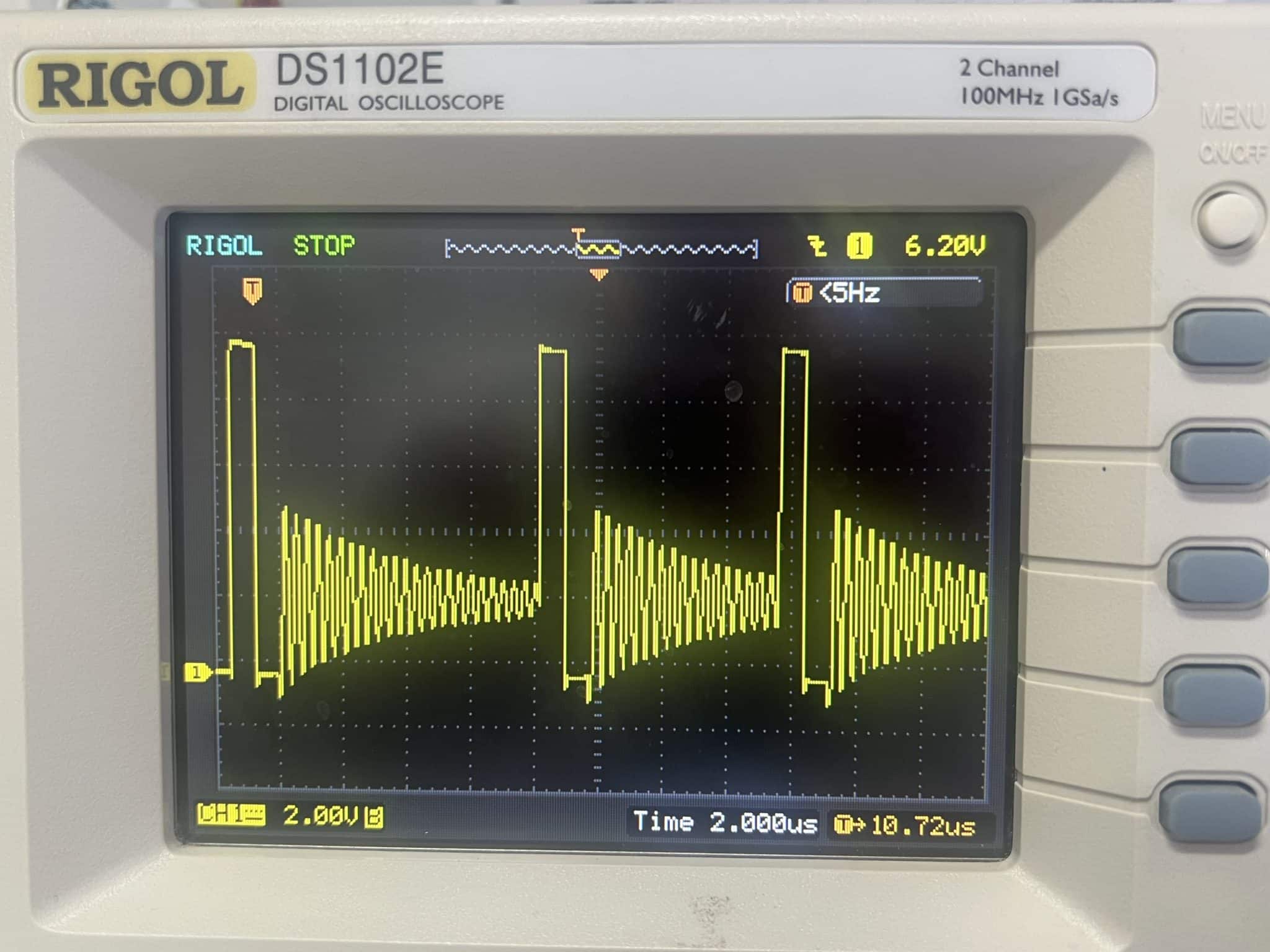
Oscilloscope testing showed good PWM control activity on all four charger gate signals:
CHGR_GATE_Q1
CHGR_GATE_Q2
CHGR_GATE_Q3
CHGR_GATE_Q4

With U7000 now generating the expected control signals, attention turned to the two power-stage packages controlled by those signals: Q7030 and Q7040.
Good PWM signals do not prove that the MOSFET power stages can transfer current correctly. A damaged package, corroded connection or compromised pad can still prevent the charging circuit from generating PPBUS_G3H.
Hidden Corrosion Was Found Under Q7040
Q7030 and Q7040 operate together in the charger’s two-phase power stage.
These two packages should be replaced as a pair if either one is faulty. This avoids leaving an aged or potentially stressed component operating beside a new one.
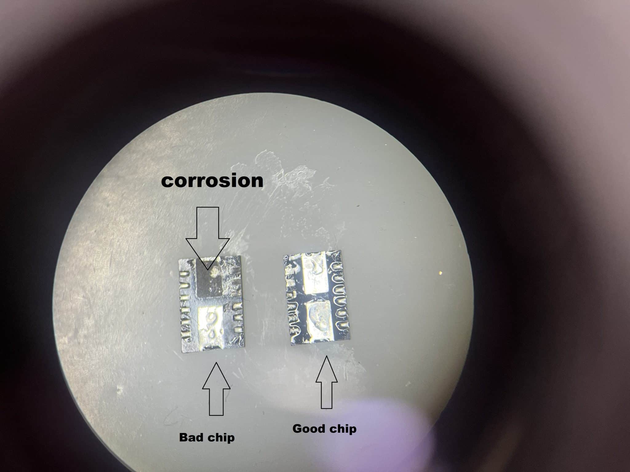
When Q7040 was removed, corrosion was discovered underneath the chip.

The corrosion had been completely concealed by the component package. It could not be seen during the initial board inspection, even with a microscope.
This explained the earlier clue at C7051 capacitor.
The affected end of C7051 capacitor was located in the same area and appeared to have been re-soldered after surface contamination or corrosion had been noticed. However, cleaning the visible area and touching up one capacitor terminal could not remove contamination that had already travelled underneath Q7040.
How Could Corrosion Develop Without a Liquid Spill?
The customer reported no liquid accident, and the board did not show the usual spread pattern associated with a drink spill.
The small and highly localised contamination pattern was consistent with insect residue or droppings.
Small insects can enter warm electronic equipment. We often encounter this type of contamination in Australian Mac repair work. The residue may attract moisture and corrode solder joints or metal surfaces while leaving the rest of the logic board looking perfectly clean.
Because the visible area had already been cleaned before the MacBook reached us, most of the original clues had disappeared.
This made the diagnosis more difficult and time-consuming. The remaining corrosion was sealed underneath a power-stage package and had to be located through advanced electronic testing before it could be physically exposed.
Components Replaced During the Final Repair
The repair included:
• Replacing the failed U7000 ISL9240 charger IC
• Replacing Q7030 and Q7040 together as a pair — high-power MOSFETs in the charger power path
• Replacing C7051 — a decoupling capacitor that stabilizes the circuit
• Replacing F7000 and F7001 — input protection fuses
• Replacing R5400 and R7060 — feedback and current-sense resistors for charge control
• Replacing L7030 — a power inductor that smooths charging current
• Ultrasonically cleaning the logic board to remove residue that might remain underneath nearby components
We renewed the surrounding components because the area had already been cleaned and reworked before the MacBook reached us. It was no longer possible to determine visually how far the original contamination had spread.
After the charger circuit was rebuilt and cleaned, normal power operation returned.
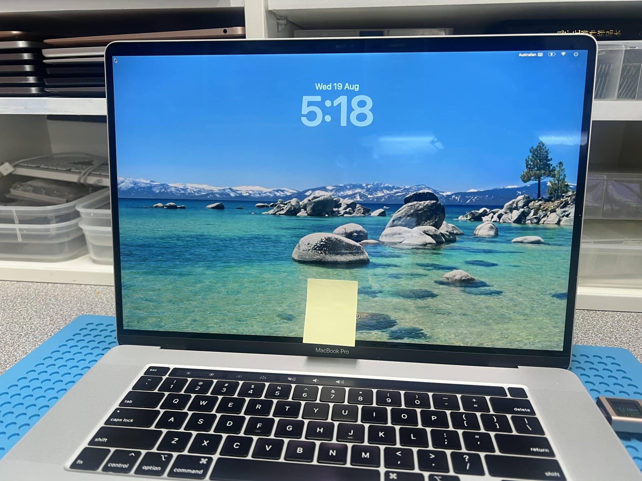
The 16-inch MacBook Pro booted from its original 820-01700 logic board, preserving the customer’s original data.

What This Repair Demonstrates
A 5 V USB-C Reading Is a Symptom, Not a Complete Diagnosis
When a MacBook remains at 5 V, the USB-C ports or USB-C controllers are not automatically faulty.
A problem farther into the charging and main power-rail circuit can prevent the machine from reaching the conditions required for normal 20 V Power Delivery operation.
One Confirmed Fault May Not Be the Entire Repair
Removing U7000 cleared a definite short, and replacing it improved PPBUS_G3H from 0.2 V to 1.8 V.
However, the main rail was still incorrect because a second fault remained in the power stage.
Checking how the board responded after each repair step was essential.
Good PWM Signals Do Not Prove the MOSFET Stage Is Healthy
The control signals for Q1 through Q4 were present, but hidden corrosion underneath Q7040 prevented the power stage from operating correctly.
Gate signals must always be considered together with the actual power-rail output and the physical condition of the switching components.
A Clean-looking Logic Board Can Still Contain Corrosion
Microscope inspection is extremely valuable, but it cannot reveal contamination sealed underneath a chip.
Electrical measurements narrowed the fault to Q7030 and Q7040. Removing Q7040 then exposed the concealed corrosion.
Repairing the Original Logic Board Can Preserve Encrypted Data
On T2-equipped MacBooks, replacing the logic board also replaces the security hardware associated with the soldered storage.
When the original logic board can be repaired safely, the MacBook and its existing data can often be recovered together.
Frequently Asked Questions
Did the Service Recommended Battery Warning Cause This Fault?
No. The worn battery required separate consideration, but it did not cause the CHGR_GATE_Q1 short or the hidden corrosion underneath Q7040.
The MacBook also failed to operate from a known-good USB-C power source, and PPBUS_G3H measured only 0.2 V.
Why Did the Charger Show Only 5 V Instead of 20 V?
Five volts is the initial USB-C supply level.
The MacBook must bring up the required control and power circuits before higher-voltage USB-C Power Delivery operation can be established. In this case, the failed charging circuit prevented that process from completing.
Why Were Q7030 and Q7040 Replaced Together?
Q7030 and Q7040 form the charger’s paired two-phase switching stage.
Replacing them together avoids operating a new component beside another device that may have experienced the same contamination, heat and electrical stress.
Can a MacBook Have Corrosion Without a Drink Being Spilled on It?
Yes. Condensation, insect residue and other small local contaminants can cause corrosion.
Some damage can also remain completely invisible underneath chips until those components are removed.
Was the Customer’s Data Preserved?
Yes. We repaired the original logic board, and the MacBook booted normally with its original T2-protected storage and data intact.
If you are interested in the deeper diagnostic side of Mac repair, we have more real logic board fault cases documented here:
Mac Logic Board Repair Case Studies
Need Board-Level Mac Repair?
We specialise in MacBook water damage repair, logic board repair, dead logic board data recovery , and component-level diagnostics.