820-01700 A2141 GPU No Display Repair – CA601 Carbonised Short and UA600 Jumper Fix
Case Summary
| Item | Details |
|---|---|
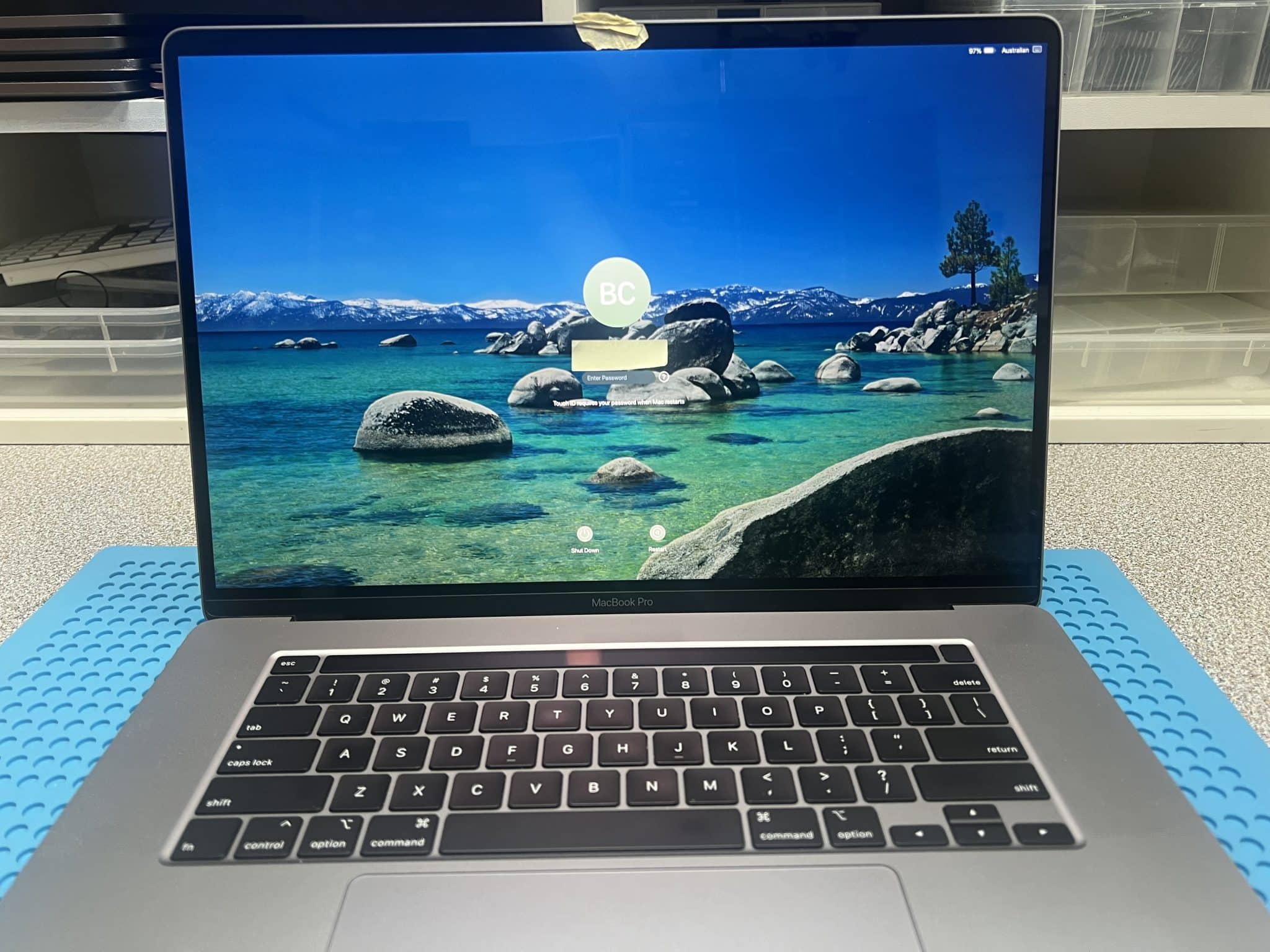
| Device | 16-inch MacBook Pro 2019 |
| Model | A2141 |
| Logic board | 820-01700 |
| Customer area | Ashburton / Ashwood VIC 3147 |
| Customer fault | Mac suddenly died, no power, no water damage |
| Initial USB-C reading | 5V / 0A |
| First short found | PP5V_G3S short |
| Short location | CA601 hot during voltage injection |
| Cause | Bug drop / carbonised area around CA601 |
| Board repair | Carbonised board removed, approx. 5 mm × 5 mm area |
| Trace repair | 3 broken surface traces repaired |
| Chip replaced | UA600 |
| After first repair | USB-C 20V with current changes |
| Remaining fault | No display |
| PMU_SYS_ALIVE | 1.8V OK |
| DISP_GCON_RESET_L | 1.8V OK |
| GPU rails | Pulsed briefly, then dropped |
| Final fault | UA600 pins 23 and 30 open |
| Final repair | Jumpers added from pins 23 and 30 to original devices |
| Final result | GPU rails stable, MacBook working |
Initial Diagnosis – PP5V_G3S Short
We started by measuring the major inductors and power rails. The first confirmed fault was:
PP5V_G3S shortedVoltage injection was used to locate the short. At around 3V injection, CA601 became hot.
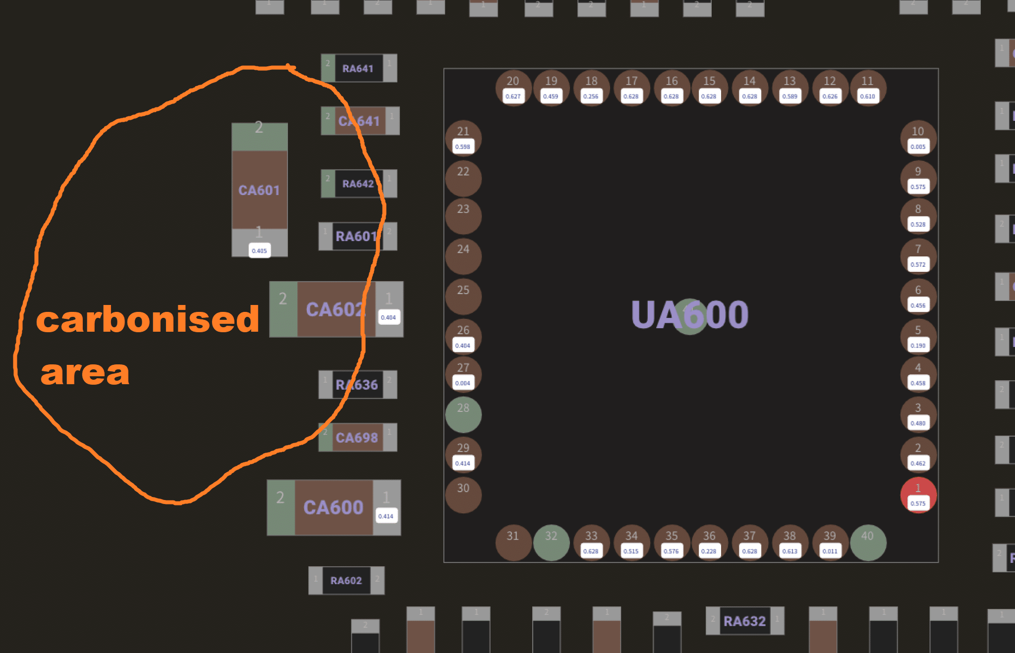
There was a bug drop on CA601, which is a very common type of contamination we see in Australia. In this case, it had carbonised and burned the board.
The damaged area was not just a failed capacitor. The PCB itself had become conductive because of the carbonised material.
The repair required:
- removing CA601;
- cutting / digging out the carbonised shorted board area, approximately 5 mm × 5 mm;
- repairing 3 broken surface-layer traces;
- replacing UA600.
After this repair, the MacBook no longer stayed at 5V / 0A.

USB-C Reading After First Repair
After the PP5V_G3S short and carbonised area were repaired, the USB-C meter changed to:
20V, 0.23A → 0.45A → 1.2A → 0.45A → 0.35AThis showed the board was now negotiating 20V and trying to boot.
However, there was still:
No display on screenAt this stage, it was not a simple no-power fault anymore. The diagnosis moved to the GPU power sequence.
No GPU Voltages on Inductors
Multimeter measurements showed no voltage on the GPU-related inductors:
LA710 / LA720 / LA730 / LA740 / LA750 = no voltage
LA850 / LA860 / LA870 = no voltage
LA900 / LA901 / LA950 = no voltage
But the start conditions were present:
PMU_SYS_ALIVE = 1.8V OK
DISP_GCON_RESET_L = 1.8V OK
This was an important clue. The system was alive and the display/GPU control reset was released, but the GPU rails were not staying on.
Oscilloscope Measurements
A multimeter only showed the GPU rails as missing, but the oscilloscope showed the real behaviour.
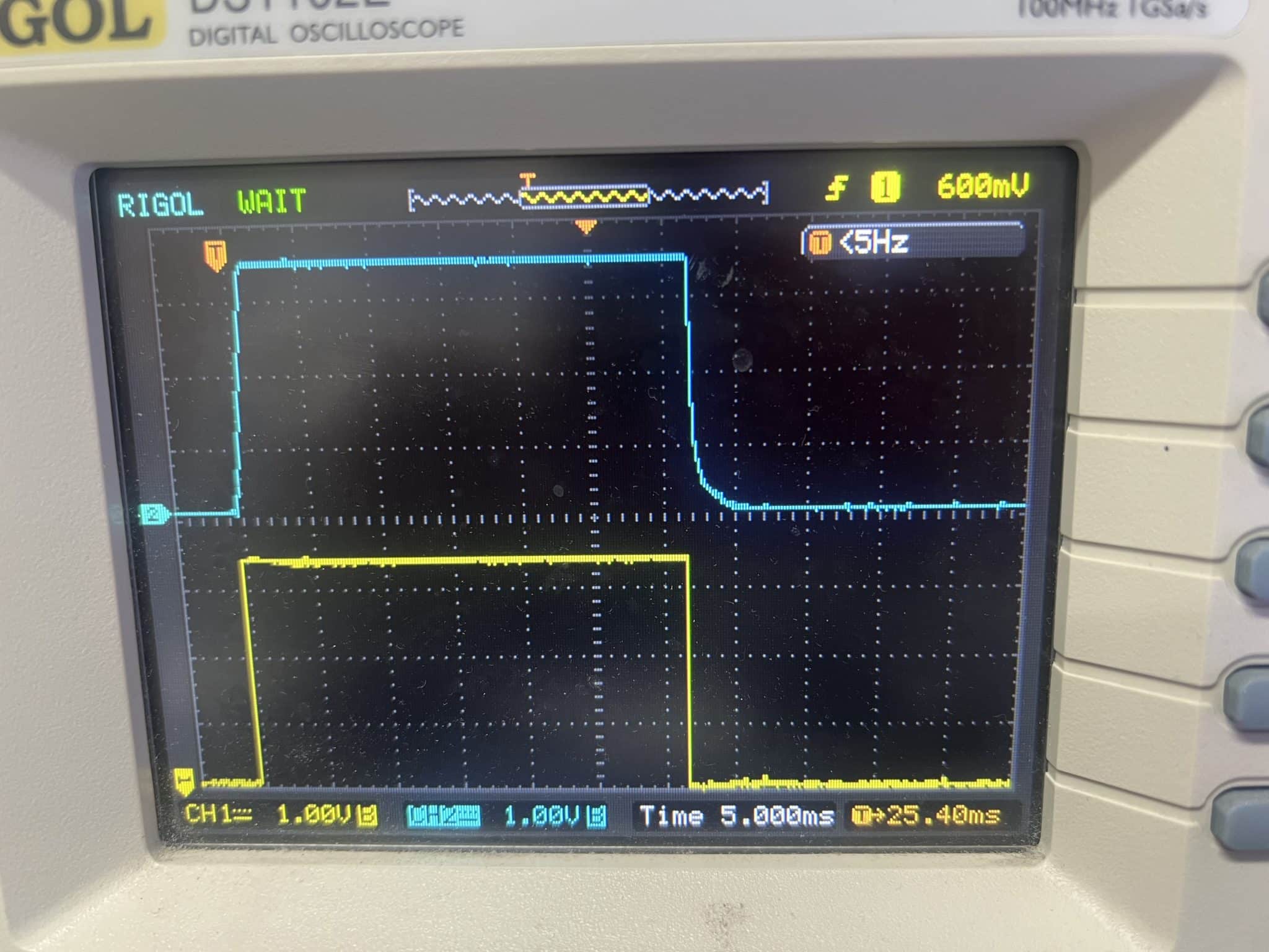
Scope measurements showed:
EG_VR0 / EG_VR1 / EG_VR2 / EG_VR3 / EG_VR4 present for about 35 ms, then drop
GPU voltages present briefly, then drop in about 30 ms
PPGFX_S0_GPU reaches target voltage, then drops in about 1 ms
The board was starting the GPU power sequence, the rails were trying to come up, but the sequence was aborted almost immediately.
That usually points to a missing PGOOD, missing sense path, open feedback / current-sense path, broken trace, or incomplete connection around the GPU regulator control circuit.

Why We Suspected Hidden Broken Connections
The earlier CA601 repair required removal of carbonised board material. That area was burned badly enough that we had to dig out approximately 5 mm × 5 mm of PCB material.
When a carbonised short is removed, the visible top-layer damage may not be the whole problem. The repair can also expose or interrupt:
- surface traces;
- thin copper around pads;
- via connections;
- hidden connections under nearby ICs;
- control or sense lines used by GPU regulators.
Because all GPU enables appeared briefly, and all GPU rails tried to start then shut down, the logic pointed away from a totally dead U9801 sequence command. It pointed more toward an incomplete regulator feedback/control path around the repaired area.
So we removed UA600 again and diode-mode checked every pin.
The key finding:
UA600 pin 23 open
UA600 pin 30 open
We connected both pins back to their original devices using jumper wires.
After that:
All GPU voltages became stable
The board worked normally
Circuit Logic
The repair logic was:
Mac suddenly died
↓
USB-C = 5V / 0A
↓
Measure major inductors
↓
PP5V_G3S short found
↓
Inject 3V
↓
CA601 hot
↓
Bug drop / carbonised board area found
↓
Remove carbonised area, repair 3 traces, replace UA600
↓
USB-C now negotiates 20V and current rises
↓
No display
↓
PMU_SYS_ALIVE = 1.8V OK
DISP_GCON_RESET_L = 1.8V OK
↓
No stable GPU voltages on LA710/720/730/740/750, LA850/860/870, LA900/901/950
↓
Scope shows EG_VR0–EG_VR4 enables appear for about 35 ms
↓
GPU rails appear briefly, then drop
↓
PPGFX_S0_GPU reaches target voltage then drops in about 1 ms
↓
GPU sequence starts but aborts
↓
Suspect broken control / sense / feedback path after carbonised board repair
↓
Remove UA600 and diode-mode all pins
↓
Pins 23 and 30 open
↓
Jumper pins 23 and 30 back to original devices
↓
GPU rails stable
↓
MacBook works
GPU Power Sequence Lesson
The key to this repair was understanding the GPU power-on sequence.
The important simplified sequence was:
| Stage | Signal / Rail | Meaning |
|---|---|---|
| Precondition | PP3V3_S5 / PP1V8_S5 | Supplies GPU control logic |
| Start request | PMU_SYS_ALIVE | System is alive and sequence can begin |
| Reset release | DISP_GCON_RESET_L | GPU/display controller logic released |
| VR0 | EG_VR0_EN → PP3V3_S0_GPU | GPU 3.3V rail starts first |
| VR1 | EG_VR1_EN → PP1V8_S0_GPU | GPU 1.8V rail starts |
| VR2 | EG_VR2_EN → PP0V75_S0_GPU | GPU 0.75V rail starts |
| VR3 | EG_VR3_EN → PPGFX_S0_GPU / PPSOC_S0_GPU | GPU graphics and SOC rails start |
| VR4 | EG_VR4_EN → memory rails | GPU memory rails start |
| Final | GPU_RESET_L | GPU released after rails are stable |
In this case, the sequence started but aborted. That was the clue. If the start request or reset path were missing, the enables would not appear. But because the enables appeared briefly, we knew the command sequence had begun.
The failure happened after the rail startup attempt.
Repair Timeline
| Step | Result |
|---|---|
| Customer reported sudden no power | Confirmed |
| USB-C meter | 5V / 0A |
| Measured inductors | PP5V_G3S short found |
| Voltage injection | CA601 hot |
| Board inspection | Bug drop / carbonised burned area found |
| Carbonised area removed | Approx. 5 mm × 5 mm board area cleaned out |
| Surface trace repair | 3 broken traces repaired |
| UA600 | Replaced |
| USB-C after first repair | 20V, current pattern appears |
| New symptom | No display |
| PMU_SYS_ALIVE | 1.8V OK |
| DISP_GCON_RESET_L | 1.8V OK |
| GPU inductors | No stable voltages |
| Scope test | EG_VR0–EG_VR4 appear for about 35 ms |
| GPU rail behaviour | Rails appear briefly then drop |
| PPGFX_S0_GPU | Reaches target then drops in about 1 ms |
| UA600 removed | Pin-by-pin diode-mode test |
| Fault found | UA600 pins 23 and 30 open |
| Final repair | Jumpers added to original devices |
| Final test | GPU rails stable, MacBook working |
Key Lesson
When a GPU rail is completely missing, it is tempting to look only for a failed regulator IC.
But in this case, the oscilloscope showed something more useful:
The GPU rails were not absent.
They were starting, then aborting.
That changed the diagnosis.
The board already had the start request and reset conditions. The GPU sequence was being commanded. The failure was in the rail completion path.
Because the board had been burned and repaired around the carbonised CA601 area, we suspected hidden open traces or missing connections. Checking UA600 pins in diode mode found the real fault: pins 23 and 30 were open.
The key lesson:
Know the GPU power sequence before replacing parts.Final Fix
The final repair included:
- PP5V_G3S short diagnosis;
- CA601 hot-spot location by voltage injection;
- removal of carbonised burned board area;
- repair of 3 broken surface traces;
- UA600 replacement;
- GPU power-sequence testing by oscilloscope;
- identification of short-lived EG_VR0–EG_VR4 enable pulses;
- confirmation that GPU rails were starting then aborting;
- UA600 pin diode-mode testing;
- jumper repair for pins 23 and 30;
- final GPU voltage stability test.
Final result:
16-inch MacBook Pro A2141 fully functionalIf you are interested in the deeper diagnostic side of Mac repair, we have more real logic board fault cases documented here:
Mac Logic Board Repair Case Studies
Need Board-Level Mac Repair?
We specialise in MacBook logic board repair, data recovery, USB-C charging faults, water damage repair and component-level diagnostics.