820-03637 A3434 No Power Repair – Severe Water Damage and UF400 Reball
Fault Description
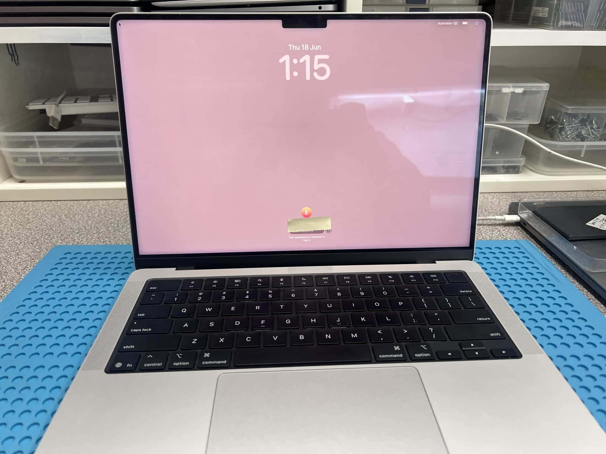
This 14-inch MacBook Pro M5 2025, model A3434, logic board 820-03637, came in from the Clayton VIC 3168 area with severe water damage and no power.
The customer explained that a water bottle opened inside a school bag and liquid ran through the MacBook. The MacBook was turned upside down and left off, then taken to a local repairer. The previous repairer tried what they could, but advised that the MacBook likely needed a new or repaired main board.
Because of the level of liquid exposure, we did not power the board on immediately. The USB-C meter test was skipped at the beginning because applying power to a badly corroded board can turn a repairable board into a non-repairable one.
Case Summary
| Item | Details |
|---|---|
| Device | 14-inch MacBook Pro M5 2025 |
| Model | A3434 |
| Logic board | 820-03637 |
| Customer area | Clayton VIC 3168 |
| Customer fault | Water bottle leaked in school bag, no power |
| Initial USB-C test | Not powered on — too risky |
| Board condition | Top side looked clean; severe corrosion found on bottom side |
| Reference used | Similar 820-02757 board view / schematic |
| Initial diagnosis method | Ultrasonic clean, diode-mode checks, voltage injection |
| Shorted rails | PPBUS_AON and PP5V_S2_UPC |
| Hot components found | CR604, CR634, CF406, CF506 |
| Corroded parts replaced | 25 capacitors, 5 resistors, 2 small IC chips |
| Post-rebuild USB-C behaviour | Two ports 5V / 0.23A rebooting; one UF400-related port 5V / 0A |
| Main boot fault | Corrosion under UF400 / SN2012024 balls |
| Repair | UF400 removed, reballed and reinstalled |
| Secondary fault | No left-side sound |
| Audio repair | UR600, UR630 and UR660 replaced |
| Final fault | Lid angle sensor not working |
| Final repair | Lid angle sensor replaced |
| Final result | MacBook fully functional |
Initial Inspection
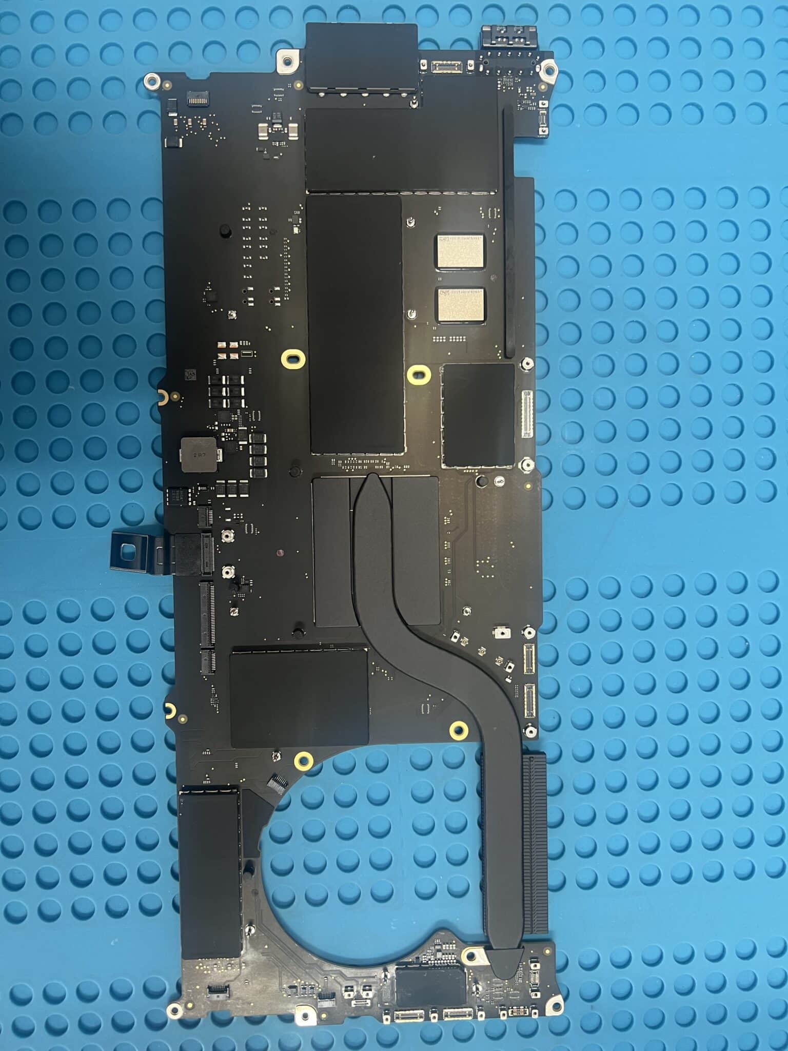
The top side of the logic board looked relatively clean, but after removing the board from the case, severe corrosion was found on the underside.
This is an important lesson. On liquid-damaged MacBooks, the visible side of the board does not always show the true damage. Liquid can travel under the board, under shields, under ICs, around connectors and into hidden low-clearance areas.
The previous repairer had not removed the board for a full underside inspection and cleaning. That is common with general repair shops, even trusted ones, because severe board-level water damage requires specific equipment, experience, schematics/board views and component-level repair skills.
Why We Did Not Power It On First
With severe corrosion, powering the board before cleaning is risky because liquid residue and corrosion can create leakage paths or direct shorts between rails.
Applying USB-C power too early can cause:
- a shorted main rail to burn pads or traces;
- PMIC or charging-circuit damage;
- NAND / CPU-related rail damage;
- corrosion to heat up and carbonise;
- small repairable faults to become board-killing faults.
For this reason, the first step was ultrasonic cleaning, followed by diode-mode checks on major power rails before any normal power-on attempt.
No 2025 Schematic Available
For this 2025 board, there was no exact schematic available. That made the job harder because there was more comparison work and more careful reasoning required.
The board layout was compared against the older 820-02757 design, which has similar areas for USB-C, power, audio and lid/sensor circuits. It is not the same board, but it gave enough reference direction to make diagnosis possible. The 820-02757 reference includes USB-C controller sections, 5V power regulation, audio sections and lid angle sensor support, which matched the fault areas we later worked through.
In this type of repair, an older similar schematic is not perfect, but it is still much better than working completely blind.
Measurements and Short-Finding Table
| Stage | Measurement / Action | Result |
|---|---|---|
| Initial USB-C power test | Not performed | Too risky to power on |
| Major rail check | PPBUS_AON | Shorted |
| Voltage injection | PPBUS_AON, started at 1V and slowly increased | CR604 and CR634 hot |
| Action | Removed CR604 and CR634 | PPBUS_AON short cleared |
| Second rail check | PP5V_S2_UPC | Shorted |
| Voltage injection | PP5V_S2_UPC, started at 1V and slowly increased to 3V | CF406 and CF506 hot |
| Action | Removed CF406 and CF506 | PP5V_S2_UPC short cleared |
| Rebuild | 25 capacitors, 5 resistors, 2 small ICs replaced | No major rail short remaining |
| First power-on after rebuild | Two ports 5V / 0.23A rebooting | Partial startup attempt |
| UF400-related port | 5V / 0A | Suspicious local USB-C controller fault |
| Microscope inspection | Corrosion under UF400 / SN2012024 balls | UF400 removed and reballed |
| After UF400 reball | Mac powered on | Boot restored |
| Audio test | No sound on left side | Secondary fault found |
| Audio IC repair | UR600, UR630, UR660 replaced | Sound restored |
| Lid close test | Mac did not sleep when lid closed | Angle sensor fault |
| Final repair | Angle sensor replaced and board ultrasonically cleaned again | Fully functional |
Why Voltage Injection Was Done Carefully
For the PPBUS_AON short, voltage injection started at 1V and was slowly increased, but not beyond the safe range for that rail.
Because PPBUS_AON is normally a high-voltage main rail, it can tolerate higher voltage than a 1.8V or 3.3V rail, but it is still dangerous to inject too much current or too much voltage into a shorted board. The purpose of injection is not to “power the MacBook”. The purpose is only to locate the shorted part by heat.
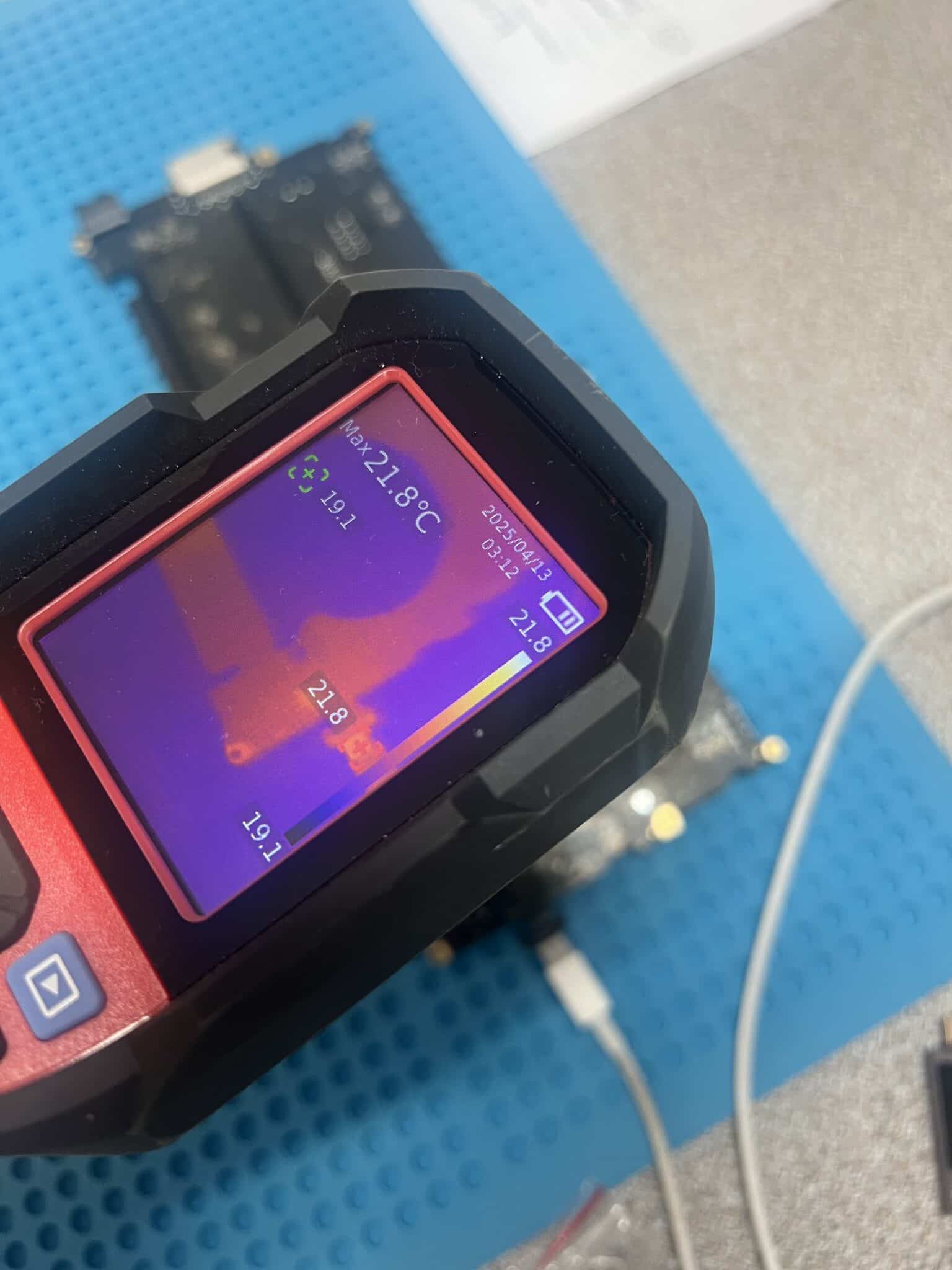
On PPBUS_AON, we slowly increased voltage and used the thermal camera. CR604 and CR634 heated up, so they were removed.
For PP5V_S2_UPC, the injection limit was lower. This is a 5V-related rail, so we started at 1V and slowly increased to around 3V. The thermal camera showed CF406 and CF506 heating, so they were removed.
This staged approach reduced the risk of causing extra damage while still allowing the shorted components to be located.
Circuit Logic
This repair had several separate fault stages.
Stage 1: Severe water damage and hidden underside corrosion
The top of the board looked clean, but the underside had severe corrosion. Because of the corrosion level, powering the board was too risky.
Correct first step:
Remove board
Inspect both sides
Ultrasonic clean
Check major power rails in diode mode
Stage 2: Main rail shorts
The first major short was:
PPBUS_AON shortVoltage injection and thermal camera testing showed:
CR604 and CR634 hotAfter removing them, the PPBUS_AON short was cleared.
The second major short was:
PP5V_S2_UPC shortVoltage injection showed:
CF406 and CF506 hotAfter removing them, the PP5V_S2_UPC short was cleared.
Stage 3: Corrosion rebuild
After short removal, no major rail short remained. We then replaced visibly corroded and high-risk components:
25 capacitors
5 resistors
2 small IC chips
This was necessary because even if a corroded component is not shorted at that exact moment, it can become unstable later under voltage, temperature or humidity.
Stage 4: UF400 / SN2012024 fault
After rebuilding the corroded area, the board was powered on for the first time.
The USB-C readings were:
Two ports: 5V / 0.23A rebooting
One UF400-related port: 5V / 0A
This pointed to a remaining USB-C controller-side fault. Under the microscope, slight corrosion was found on the balls under UF400 / SN2012024.
The chip was removed, reballed and reinstalled. After that, the MacBook powered on.
This makes sense because a BGA USB-C controller may look acceptable from the outside, but corrosion under the solder balls can break communication, create leakage, or stop the controller from waking correctly.
Stage 5: Left-side sound fault
After the MacBook booted, left-side sound was not working.
The audio section was then inspected and repaired. UR600, UR630 and UR660 were replaced. Corrosion was found after removing the chips, confirming that the fault was hidden underneath.
After replacing these ICs, the sound issue was fixed.
Stage 6: Lid angle sensor fault
The final functional fault was the lid / angle sensor. When closing the top case, the system did not go to sleep.
The angle sensor was replaced, and the lid sleep function returned to normal.
The board was ultrasonically cleaned again before final testing.

Repair Timeline
| Step | Result |
|---|---|
| Customer reported water bottle leak and no power | Confirmed |
| USB-C meter test | Skipped because powering on was too risky |
| Removed back case | Top side looked clean |
| Removed board | Severe underside water damage found |
| First ultrasonic clean | Completed before electrical testing |
| No exact 2025 schematic | Used similar 820-02757 board view / schematic as reference |
| Diode-mode test | PPBUS_AON short found |
| Voltage injection on PPBUS_AON | CR604 and CR634 hot |
| Removed CR604 and CR634 | PPBUS_AON short cleared |
| Diode-mode test | PP5V_S2_UPC short found |
| Voltage injection on PP5V_S2_UPC | CF406 and CF506 hot |
| Removed CF406 and CF506 | PP5V_S2_UPC short cleared |
| Replaced corroded parts | 25 capacitors, 5 resistors, 2 small IC chips |
| Power-on attempt | Two ports 5V / 0.23A rebooting, one port 5V / 0A |
| Microscope inspection | Corrosion under UF400 / SN2012024 balls |
| UF400 repair | Removed, reballed and reinstalled |
| Result | Mac powered on |
| Audio test | No sound on left side |
| Audio repair | UR600, UR630, UR660 replaced |
| Result | Sound fixed |
| Lid close test | Mac did not sleep |
| Sensor repair | Angle sensor replaced |
| Final cleaning | Ultrasonic clean again |
| Final result | Mac fully functional |
Key Lesson
Severe water damage is often hidden. A MacBook logic board can look clean on the top side while the underside is badly corroded.
The most important lessons from this case are:
- Do not power on a severely water-damaged board before inspection and cleaning.
A normal USB-C power test can make the damage worse. - Check major rails in diode mode first.
PPBUS_AON and PP5V_S2_UPC shorts were found before normal power was applied. - Use controlled voltage injection, not full power.
Injecting carefully allowed the thermal camera to locate CR604, CR634, CF406 and CF506 without powering the whole board. - A similar schematic is still useful when the exact one is unavailable.
It does not remove all guesswork, but it gives direction. - After the Mac boots, keep testing.
This board still had left-side sound and lid angle sensor faults after the no-power issue was fixed.
Final Fix
The final repair included:
- full board removal and underside inspection;
- ultrasonic cleaning before power-on;
- diode-mode checks on major rails;
- voltage injection and thermal-camera short finding;
- CR604 and CR634 removed from PPBUS_AON short;
- CF406 and CF506 removed from PP5V_S2_UPC short;
- replacement of 25 capacitors, 5 resistors and 2 small IC chips;
- UF400 / SN2012024 removed, reballed and reinstalled;
- UR600, UR630 and UR660 replaced for left-side sound;
- angle sensor replaced for lid sleep function;
- second ultrasonic clean;
- final functional testing.
Final result:
MacBook fully functionalIf you are interested in the deeper diagnostic side of Mac repair, we have more real logic board fault cases documented here:
Mac Logic Board Repair Case Studies
If you have a water-damaged MacBook Pro, especially a newer model where Apple or another repairer has recommended main board replacement, contact IT-Tech Online before replacing the whole board.
We specialise in MacBook logic board repair in Melbourne, including severe water damage, no-power faults, USB-C power faults, shorted rails and board-level component repair.


