820-03400 A3401 No Power After Screen Replacement – UD950 Fault
Fault Description
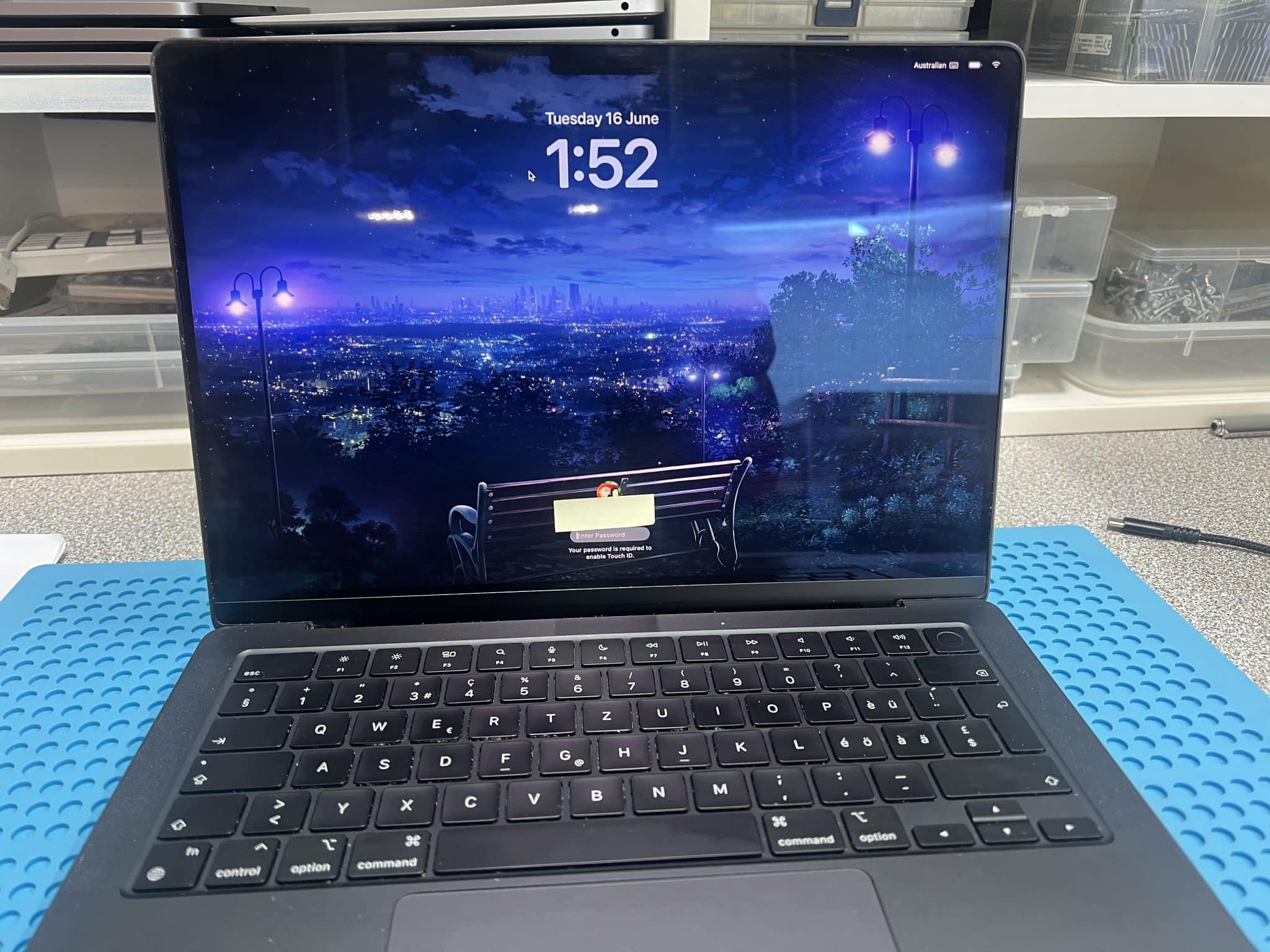
This 14-inch MacBook Pro M4 2024, model A3401, logic board 820-03400, came from a computer shop that provides screen replacement service.
The original fault was a broken screen, but the MacBook could still power on before the screen was replaced. After the replacement screen was connected, the MacBook stopped powering on.
Initial USB-C meter reading:
5V / 0.5A stableThat reading showed the board was taking some current, but it was not moving into normal boot behaviour.
Because the failure happened directly after a screen replacement, the first diagnostic direction was the screen / webcam / camera connector area, not the USB-C charging circuit.
Case Summary
| Item | Details |
|---|---|
| Device | 14-inch MacBook Pro M4 2024 |
| Model | A3401 |
| Logic board | 820-03400 |
| Customer area | Craigieburn / Northern suburbs VIC 3064 |
| Customer source | Computer shop doing screen replacement |
| Original condition | Mac powered on with broken screen |
| Fault after repair attempt | No power after replacement screen fitted |
| USB-C meter | 5V / 0.5A stable |
| 820-03400 schematic / board view | Not available |
| Reference used | Similar 820-02918 board view / schematic |
| Suspected area | Screen connector / webcam / ALS power rail |
| Wrong screen clue | Replacement screen had corresponding pins 29 and 30 connected |
| Good 820-03400 board | Pin 29 = 5V, pin 30 = 1.8V |
| Faulty 820-03400 board | Pin 29 = 5V, pin 30 = 0V |
| Pin 30 diode mode | 0, shorted |
| Short location method | Injected 1V into pin 30 |
| Hot component | UD950 |
| Repair | Removed and replaced UD950 |
| Final result | MacBook powered on and worked |
Why We Checked the Screen Connector First
The fault appeared immediately after screen replacement. That is the key clue.
If the MacBook powered on before the display was replaced, but would not power on after the new display was connected, the most logical first check is the connector and screen-related power rails.
On newer MacBooks, the display assembly is not just a screen. It also carries circuits for the webcam, ALS sensor and related data/power lines. If the wrong screen generation is connected, the connector may physically fit, but the pin assignment may not be electrically safe.
In this case, the connector shape was not enough to confirm compatibility.
Reference Schematic Problem
There was no exact 820-03400 board view / schematic available for this M4 model.
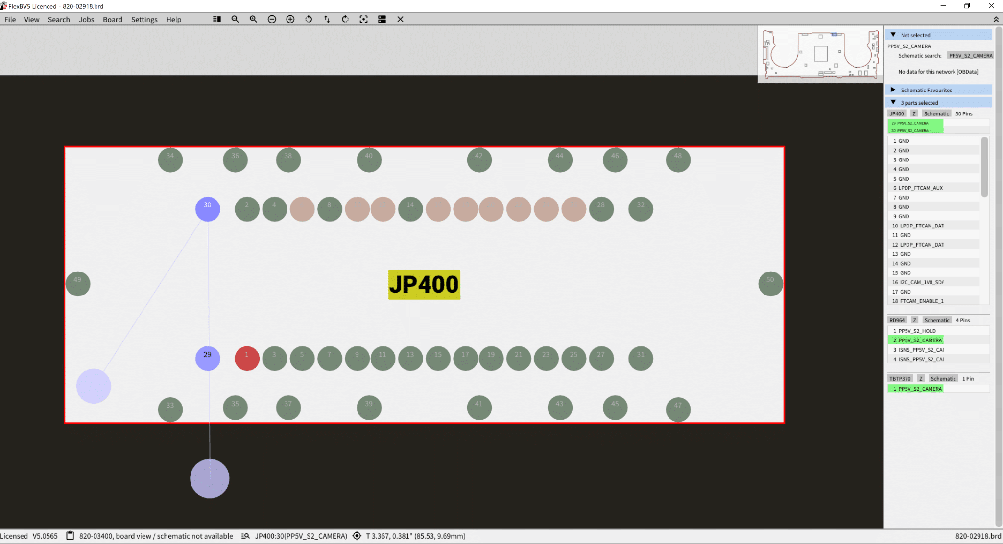
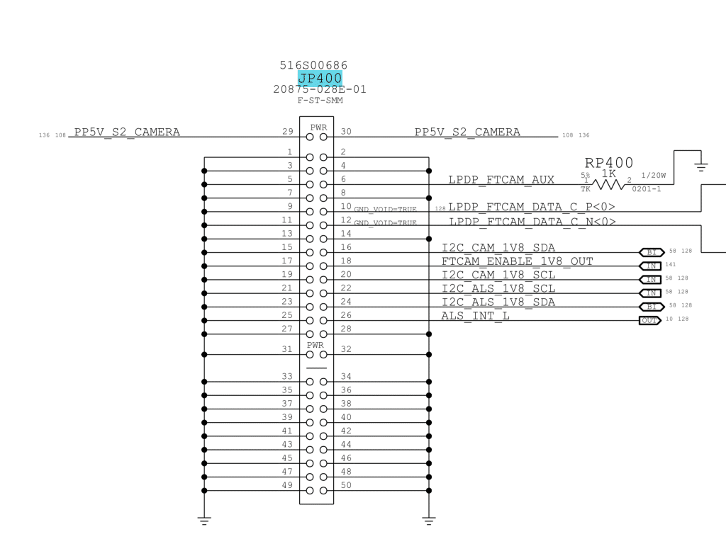
So we used a similar 820-02918 board view / schematic as a reference. This is not ideal, but it is better than working blind. The 820-02918 reference shows the camera flex connector area, JP400, PP5V_S2_CAMERA and connector type 20875-028E-01, which helped guide the comparison.
The key was not to assume the older reference was identical. Instead, we used it to understand the older connector design, then compared it against a known-good 820-03400 M4 board.
Connector Pin Logic
On a known-good 820-02918 board:
JP400 pin 29 = PP5V_S2_CAMERA
JP400 pin 30 = PP5V_S2_CAMERA
Pins 29 and 30 are connected together to provide the 5V camera / ALS power rail.
The replacement screen had the corresponding pins to board pin 29 and pin 30 connected together. That strongly suggested the replacement screen was an M1–M3 generation screen, not an M4/M5 screen.
On a known-good 820-03400 M4 board:
Pin 29 = 5V
Pin 30 = 1.8V
So the M4 board is different. Pin 30 is no longer the same 5V camera rail. It is a lower-voltage rail.
On the faulty board:
Pin 29 = 5V
Pin 30 = 0V
Pin 30 diode mode = 0
That means pin 30 was shorted.
How the Wrong Screen Damaged the Board
The replacement screen had the corresponding pins 29 and 30 connected together. On an older M1–M3 style design, this is expected because both pins are used for the 5V camera power path.
But on the M4 board, pin 30 should be a 1.8V rail.
When the wrong screen was connected, the screen effectively bridged or injected the 5V PP5V_S2_CAMERA rail into the 1.8V pin 30 rail.
That is dangerous because a 1.8V circuit is not designed to receive 5V. The result can be:
- immediate short on the 1.8V rail;
- damaged regulator or load IC;
- damaged camera / ALS support circuit;
- no-power or stuck low-current USB-C behaviour;
- board failure even though the connector physically fits.
In this case, pin 30 became shorted to ground, and the MacBook stayed at 5V / 0.5A stable instead of booting.
Measurements Table
| Test / Observation | Result |
|---|---|
| USB-C meter | 5V / 0.5A stable |
| Board view / schematic for 820-03400 | Not available |
| Reference used | Similar 820-02918 |
| Replacement screen pin check | Corresponding pins 29 and 30 connected |
| Known-good 820-03400 pin 29 | 5V |
| Known-good 820-03400 pin 30 | 1.8V |
| Faulty 820-03400 pin 29 | 5V |
| Faulty 820-03400 pin 30 | 0V |
| Pin 30 diode mode | 0, shorted |
| Voltage injection | 1V into pin 30 |
| Hot component | UD950 |
| Repair | Replaced UD950 |
| Final result | MacBook working |
Circuit Logic
The repair logic was:
Mac powered on before screen replacement
↓
No power after replacement screen connected
↓
USB-C meter stuck at 5V / 0.5A
↓
Fault likely related to display / camera / ALS connector
↓
No exact 820-03400 schematic available
↓
Use 820-02918 as reference, then compare with known-good 820-03400 board
↓
Replacement screen has pin 29 and pin 30 connected
↓
This matches older M1–M3 style screen wiring
↓
Good 820-03400 board has pin 29 = 5V, pin 30 = 1.8V
↓
Wrong screen injected 5V into the 1.8V rail
↓
Faulty board pin 30 = 0V, diode mode = 0
↓
Inject 1V into pin 30
↓
UD950 heats
↓
Replace UD950
↓
MacBook works
Why Inject Only 1V Into Pin 30
Pin 30 was expected to be a 1.8V-related rail, not a high-voltage rail.
Because the rail was shorted, injecting too much voltage or current could damage more components. The purpose of voltage injection was not to power the board. It was only to locate the shorted part by heat.
So we injected a controlled 1V into pin 30. UD950 heated up, confirming the fault area.
After removing/replacing UD950, the short was gone and the MacBook powered on normally.

Repair Timeline
| Step | Result |
|---|---|
| Computer shop replaced broken screen | Mac stopped powering on |
| USB-C meter test | 5V / 0.5A stable |
| Checked screen connector first | Fault appeared after screen replacement |
| Used 820-02918 reference | Compared camera connector design |
| Checked replacement screen pins | Corresponding pins 29 and 30 connected |
| Compared with good 820-03400 board | Pin 29 = 5V, pin 30 = 1.8V |
| Checked faulty board | Pin 29 = 5V, pin 30 = 0V |
| Diode mode on pin 30 | 0, shorted |
| Injected voltage into pin 30 | 1V controlled injection |
| Thermal result | UD950 hot |
| Repair | Replaced UD950 |
| Final test | MacBook powered on and worked |
Key Lesson
A screen connector that physically fits does not guarantee the screen is electrically compatible.
On this M4 MacBook Pro, the replacement screen appeared to fit, but the webcam / camera circuit design was different. The older-style screen connected a 5V camera rail to a pin that should be 1.8V on the M4 board.
The key lesson:
For M4/M5 screen replacement, check screen generation and connector pin mapping before powering the board.If the wrong screen is connected, it can damage the logic board.
Final Fix
The final repair was:
- confirmed MacBook stopped powering on after screen replacement;
- confirmed USB-C reading of 5V / 0.5A stable;
- checked the screen connector first;
- used 820-02918 reference and known-good 820-03400 comparison;
- identified wrong-generation screen pin connection;
- confirmed pin 30 was shorted;
- injected 1V into pin 30;
- located hot UD950;
- replaced UD950;
- confirmed MacBook powered on and worked.
If you are interested in the deeper diagnostic side of Mac repair, we have more real logic board fault cases documented here:
Mac Logic Board Repair Case Studies
Need Board-Level Mac Repair?
We specialise in MacBook logic board repair, USB-C charging faults, water damage repair and component-level diagnostics.


